

Method for detecting and controlling laser metal forming height on line
A metal forming and high-level technology, applied in metal material coating process, measuring device, using optical device, etc., to achieve the effect of uniform growth of height and smooth surface of laser forming
Inactive Publication Date: 2010-11-24
XI AN JIAOTONG UNIV +1
View PDF9 Cites 29 Cited by
- Summary
- Abstract
- Description
- Claims
- Application Information
AI Technical Summary
Benefits of technology
This patented technique allows for precise placement of small metallic plates on surfaces by controlling how much energy from an external source can be used during formation. By doing this, these techniques allow for more efficient use of materials while maintaining smooth surfaces without causing damage or defects over time.
Problems solved by technology
The technical problem addressed in this patented text relates to improving the formation precision for metallic components during laser melting processes caused by various factors such as temperature fluctuations or material shrinkage over time. These effects may lead to poorly formed part shapes leading to reduced functionality and durability compared to regular production techniques.
Method used
View moreImage
Smart ImageViewing Examples


Examples
Embodiment Construction
Login to View More PUM
 Abstract
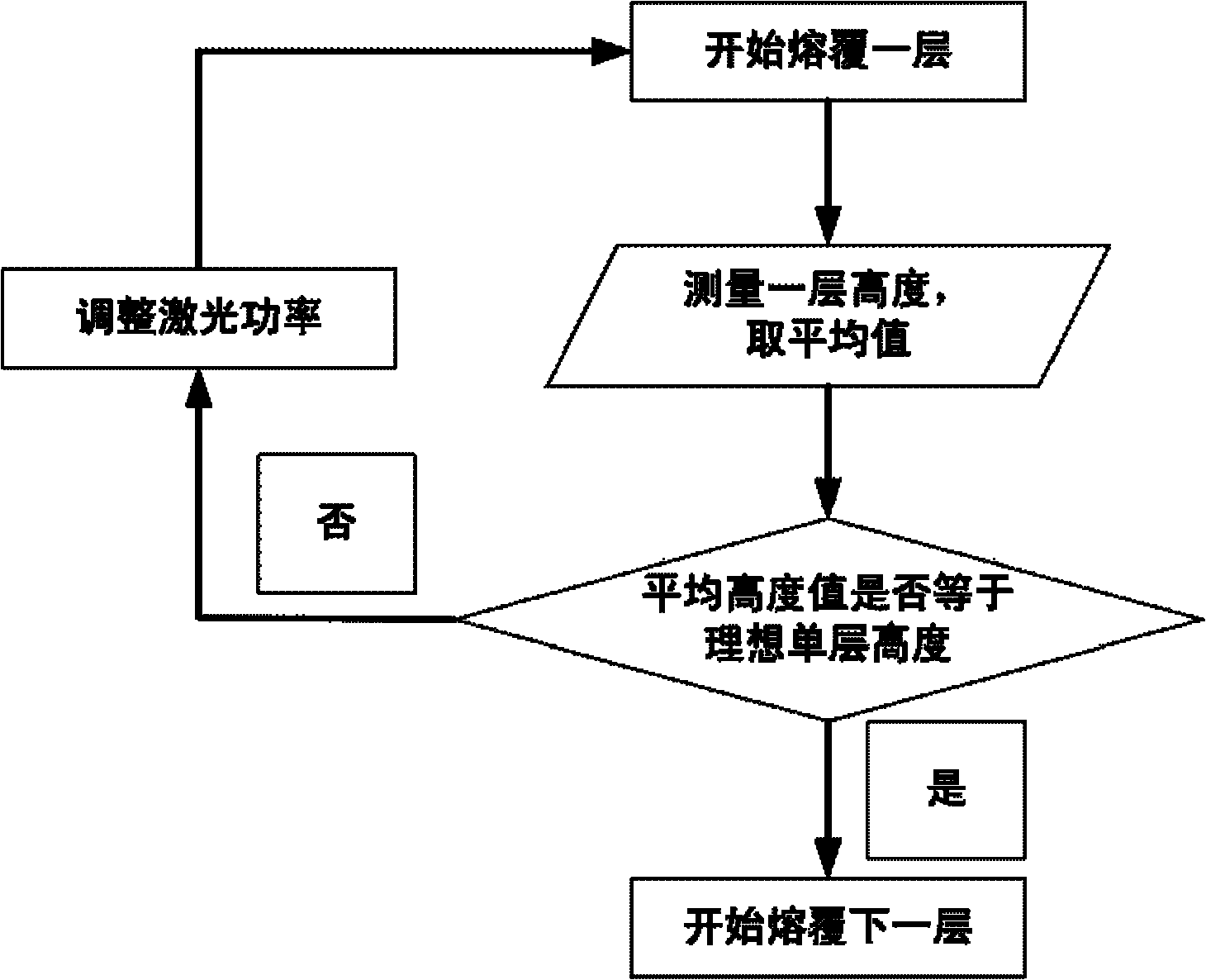
The invention discloses a method for detecting and controlling laser metal forming height on line. The method comprises the following steps of: vertically mounting a laser displacement sensor on a coaxial powder feeding nozzle; ensuring that laser emitted from the sensor is parallel to the laser emitted from a laser device; opening the laser device and performing cladding forming on the substrate by using a computer numerical control system; after a first layer is formed, controlling sensor offset by using the computer numerical control system; moving a detected surface below the sensor; ensuring that the laser emitted from the sensor is reflected by the detected surface and then received and output by a receiver of the sensor; averaging cladding height data by using the computer numerical control system; comparing an average with an ideal single-layer height; if the average is different from the ideal single-layer height, making the increased height of a cladding consistent with the ideal single-layer height by adjusting the power of the laser device; and continuing performing next cladding and height detection until a component is formed to a needed height by cladding, wherein the laser power is adjusted to gradually reduce along with the change of accumulation layers so as to ensure the uniform growth of the height of each layer.
Description
Login to View More Claims
Login to View More Application Information
Patent Timeline
 OwnerXI AN JIAOTONG UNIV