Method and apparatus for manufacturing a battery terminal with undercut rings

a technology of undercut rings and battery terminals, which is applied in the direction of cell components, manufacturing tools, cell component details, etc., can solve the problems of limiting the shape of annular rings, unsatisfactory porosity of finished battery terminals, and high cost of environmentally safe implementation, so as to facilitate the manufacture of battery terminals and prevent electrolyte leakage , the effect of improving sealing properties

Inactive Publication Date: 2006-04-04
TULIP MOLDED PLASTICS CORP
View PDF16 Cites 33 Cited by
  • Summary
  • Abstract
  • Description
  • Claims
  • Application Information

AI Technical Summary

Benefits of technology

[0010]The present invention facilitates the manufacture of battery terminals that provide improved sealing properties for preventing leakage of electrolyte.

Problems solved by technology

This is disadvantageous in that melting the lead alloy may create undesirable porosity in the finished battery terminal and is expensive to implement in an environmentally safe manner.
In addition, the multi-part mold used in the hot forming process imposes design constraints on the battery terminal in that the various elements of the battery terminal must be shaped so that the battery terminal can be removed from the mold once the lead alloy has cooled.
As with the multi-part molds of the hot forming process, the use of a split die to form a battery terminal with annular rings in the cold forming process limits the shape of the annular rings.
In particular, the annular rings must not have any undercut or overhang because that would make it impossible to remove the battery terminal after forming is complete.
It has been found, however, that annular rings having such simple profiles can result in leakage of electrolyte as the plastic material surrounding the battery terminal shrinks over time.

Method used


Image

  • Method and apparatus for manufacturing a battery terminal with undercut rings
  • Method and apparatus for manufacturing a battery terminal with undercut rings
  • Method and apparatus for manufacturing a battery terminal with undercut rings

Examples


Embodiment Construction

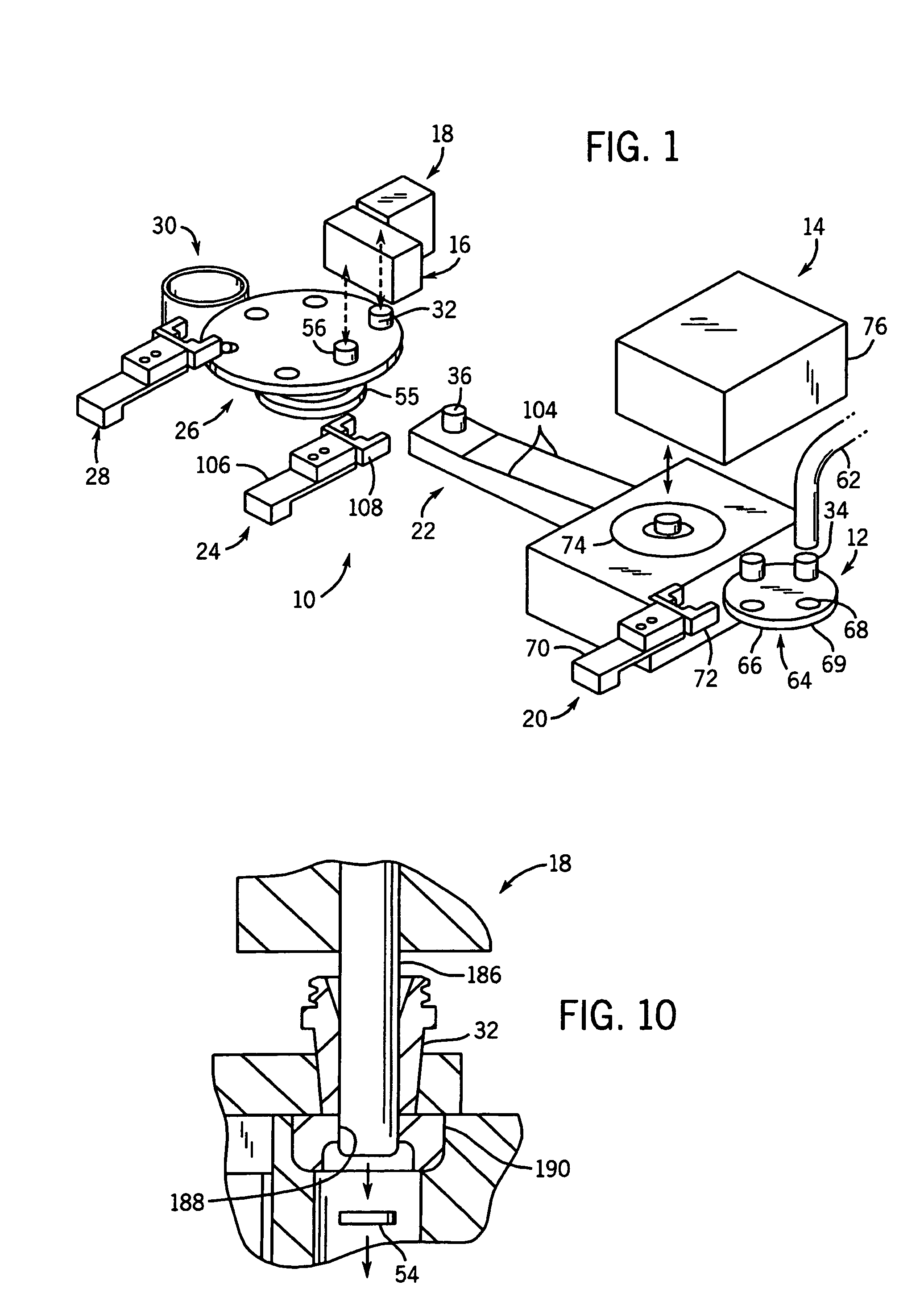
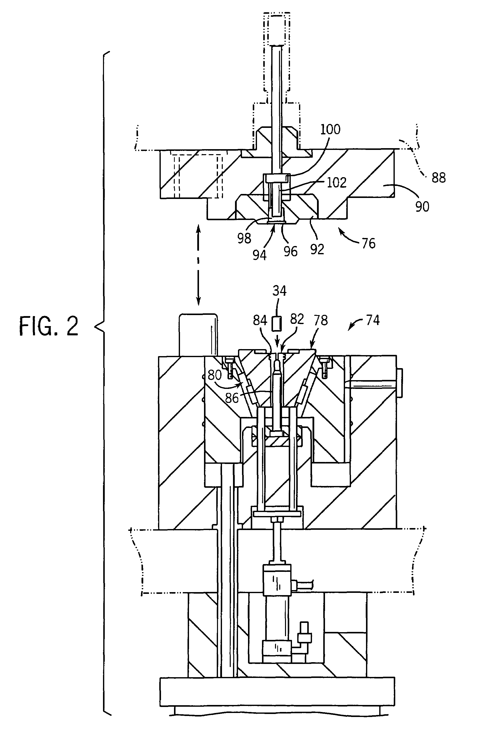
[0038]Referring to FIG. 1, a battery terminal forming apparatus 10 includes four stations: a lead slug station 12, a forming station 14, a radial rolling station 16, and a through punch station 18. Additionally, apparatus 10 includes a first pick and place transfer mechanism 20, a vibratory transfer mechanism 22, a second pick and place transfer mechanism 24, an index (or fixture) assembly 26, a third pick and place transfer mechanism 28, and a drop station 30.

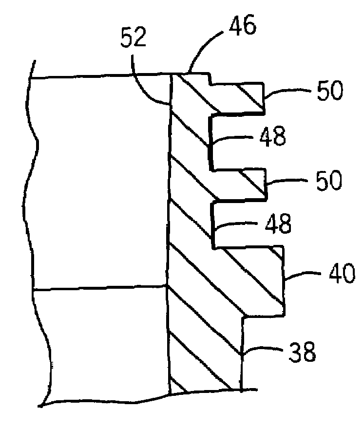
[0039]Apparatus 10 creates a finished battery terminal 32 (see FIG. 11F) from a lead slug 34 (see FIG. 11A). Lead slug 34 is first transferred from lead slug station 12 to forming station 14 with first pick and place transfer mechanism 20. In forming station 14, lead slug 34 is cold pressed into a semi-finished battery terminal 36 (see FIG. 11B) including a frustum 38 having a frusto-conical shape, a splined ring 40 having a plurality of splined ring recesses 42 and tabs 44, a head 46 having a base (or root) diameter surface 4...


PUM

PropertyMeasurementUnit
angleaaaaaaaaaa
angleaaaaaaaaaa
widthaaaaaaaaaa

Abstract

A method and apparatus utilizing a radial rolling process to cold form rings on a lead battery terminal with undercuts or overhangs to improve the sealing properties of the rings. The apparatus includes a fixture configured to securely position the battery terminal beneath a rolling station. The rolling station includes a radial rolling spindle having a plurality of cam shaped rollers configured to transform at least one ring on the battery terminal from having an initial rectangular cross-sectional shape into a desired arrowhead cross-sectional shape when the terminal and cold metal forming member are rotated relative to each other. A drive assembly is configured to rotate the battery terminal and radial rolling head relative to each other.

Description

CROSS REFERENCE TO RELATED APPLICATIONS[0001]The present application is a continuation of U.S. patent application Ser. No. 09 / 881,261, filed Jun. 14, 2001 now U.S. Pat. No. 6,644,084, titled “Method and Apparatus for Manufacturing a Battery Terminal with Undercut Rings” and is incorporated by reference herein.FIELD OF THE INVENTION[0002]The present invention relates generally to an apparatus and method for cold forming of a ring on a lead battery terminal. More specifically, the invention relates to an apparatus and method for radial rolling undercut rings on a lead battery terminal.BACKGROUND OF THE INVENTION[0003]In general, battery terminals are utilized as an interface between a sealed battery container and an external device seeking electrical power. In sealed batteries containing liquid electrolyte, the battery terminal must be configured to prevent leakage of electrolyte to ensure the battery will not fail prematurely when called upon. This is especially important in today's ...

Claims


Application Information

Patent Timeline
Patent Type & Authority Patents(United States)
IPC IPC(8): B21B15/00B21H7/18B21J5/12H01M10/06H01M50/552H01M50/562H01M50/564
CPCB21H7/182H01M2/305B21J5/12H01M10/06Y02E60/10H01M50/562H01M50/564H01M50/552
Inventor SPIEGELBERG, BERNARD N.
Owner TULIP MOLDED PLASTICS CORP
Why Eureka
Try Eureka