Power failure alarm circuit and control method thereof

A control method and electrical alarm technology, applied in the direction of measuring current/voltage, measuring electrical variables, measuring devices, etc., can solve problems such as increase in capacitor volume, electrolyte leakage, bulging, etc., and meet the requirements of reducing consumption time and capacity. , the effect of reducing the volume specification

Inactive Publication Date: 2019-07-26
FENGHUO COMM SCI & TECH CO LTD
View PDF7 Cites 3 Cited by
  • Summary
  • Abstract
  • Description
  • Claims
  • Application Information

AI Technical Summary

Problems solved by technology

[0005] At present, this method of directly dividing the voltage of the input voltage of the equipment power supply and directly placing the energy storage capacitor has the following shortcomings: 1: The peripheral interface of the equipment increases, and the power consumption required is also greater, so the capacitance required for the power-off alarm The capacity is also larger, the cost is too high
2: Large-capacity electrolytic capacitors will occupy more PCB space in PCB board design, and the increase in capacitor volume will also easily interfere with the structure and other issues.
3: Capacitors with large capacity are more prone to problems such as electrolyte leakage and bulging, resulting in quality risks

Method used


Image

  • Power failure alarm circuit and control method thereof
  • Power failure alarm circuit and control method thereof
  • Power failure alarm circuit and control method thereof

Examples


Embodiment Construction

[0033] The present invention will be described in further detail below in conjunction with the accompanying drawings and embodiments.

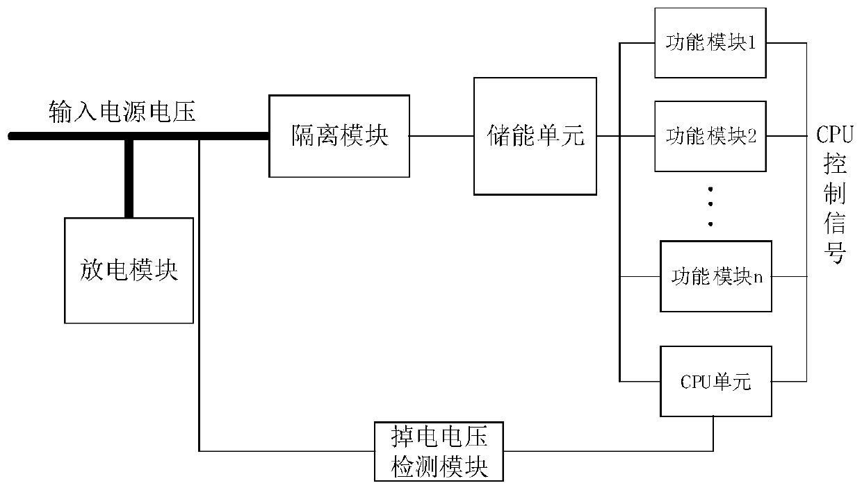
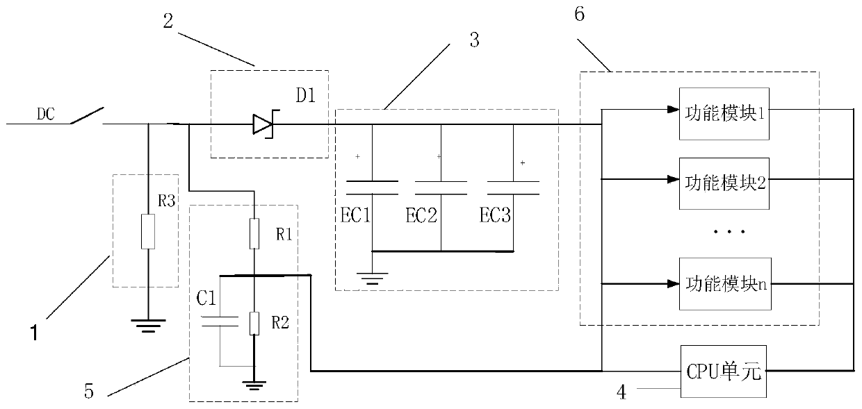
[0034] see figure 1 As shown, the embodiment of the present invention provides a power-down alarm circuit, which includes a discharge module, an isolation module, an energy storage unit, a power-down voltage detection module and a CPU unit. see also figure 2 shown in figure 2 In the circuit diagram, the discharge module is marked as 1, the isolation module is marked as 2, the energy storage unit is marked as 3, the CPU unit is marked as 4, the power-down voltage detection module is marked as 5, and the power consumption circuit is marked as 6. There are n function modules on it.

[0035] Wherein, the discharge module has an input terminal for connecting with an input power supply. The discharge module is mainly used to quickly drop the voltage of the input power supply below the power failure detection threshold of the CPU unit when the ...


PUM


Abstract

The invention discloses a power failure alarm circuit and a control method thereof, and relates to the field of power failure alarm circuits. The power failure alarm circuit comprises a discharge module, an isolation module and a power failure electric voltage detecting module, wherein the input end of the discharge module is used for being connected with an input power supply; the input end the of the isolation module is used for being connected with the input power supply, the output end of the isolation module is connected with the input end of an energy storage unit, and the output end ofthe energy storage unit is used for being connected with a function module of terminal equipment; the input end of the power failure electric voltage detecting module is connected between the discharge module and the isolation module, the output end of the power failure electric voltage detecting module is used for being connected with the function module, a CPU is arranged between the output endof the power failure electric voltage detection module and the function module, the power failure electric voltage detecting module is used for detecting the voltage of the input power supply, after voltage dividing is carried out, the divided voltage is transmitted to the CPU, and the CPU is used for judging whether the divided voltage is less than a preset power failure detection threshold or not. The power failure alarm circuit and the control method thereof is suitable for a PON gateway, a set-top box, a fusion terminal and other terminal equipment, and the voltage of the input power supply is enabled to be rapidly reduced, so that the capacity, cost and size of an energy storage unit are reduced.

Description

technical field [0001] The invention relates to the field of power-down alarm circuits, in particular to a power-down alarm circuit and a control method thereof. Background technique [0002] In the communication system, after the terminal equipment is powered off, the terminal equipment needs to report the power-down alarm information to the central office equipment. After receiving this information, the central office equipment performs corresponding processing and recording, and marks the power-down alarm for the power-down terminal equipment. State, this function is the power-down alarm (DyingGasp) function. [0003] When the terminal equipment is powered off, in order to realize the function of reporting power-down alarm information to the central office equipment, a corresponding power-down alarm circuit must be designed in the circuit design of the terminal equipment. The current common practice is to place a large-capacity energy storage capacitor at the input power...

Claims


Application Information

Patent Timeline
Patent Type & Authority Applications(China)
IPC IPC(8): G01R19/165
CPCG01R19/16538
Inventor 朱梦霞赵妮丽
Owner FENGHUO COMM SCI & TECH CO LTD
Why Eureka
Try Eureka