High rate charging and discharging cylindrical secondary battery

a secondary battery, high-rate technology, applied in the manufacture of batteries, cell components, final products, etc., can solve the problems of contact surfaces, secondary battery cannot provide uniform output, etc., to achieve defective product rate, large stress, and partial breakage of vents

Active Publication Date: 2011-12-06
LG ENERGY SOLUTION LTD
View PDF12 Cites 2 Cited by
  • Summary
  • Abstract
  • Description
  • Claims
  • Application Information

AI Technical Summary

Benefits of technology

[0015]As a result of a variety of extensive and intensive studies and experiments to solve the problems as described above, the inventors of the present invention have found that, when the outer surface of a top cap is surrounded by the end of a vent, and a groove is formed at the interface between the vent and the top cap, the increase of the contact resistance is restrained even when external forces, such as vibrations or impacts, are applied to a battery, the leakage of an electrolyte out of the battery is prevented, and the defective product rate is considerably decreased during the assembly of the battery. In addition, the inventors of the present invention have found that, when a welding operation is performed adjacent to the outer circumferential surface of the top cap at the above-described structure, the welded region is not exposed to the outside, whereby the reduction of a coupling force due to the degradation of the welded part caused by the long-term use of the battery is restrained, and therefore, the increase of the contact resistance is restrained. The present invention has been completed based on these findings.
[0028]During the vertical bending process and the horizontal bending process, on the other hand, an end region (A) of the vent corresponding to the outer circumferential surface of the top cap is greatly deformed. As a result of many trials and errors and various experiments, the inventors of the present invention have found that, when the above-described process is continuously carried out, large stress is concentrated on the end region (A) of the vent, and therefore, the partial breakage of the vent (i.e., the defective product rate) is increased.

Problems solved by technology

However, it has been proven that it is difficult for the secondary battery with the above-stated construction to provide instantaneously high output, and the resistance of the contact surfaces of the secondary battery is increased when external impacts, such as vibration, is applied to the secondary battery, whereby it is difficult for the secondary battery to provide uniform output.
Nevertheless, the secondary battery with the above-stated construction has a problem in that, when external impacts, such as vibration, are applied to the secondary battery, the resistance at the contact surfaces between the top cap 41, the PTC element 42, the vent 43, and the cap plate 45 is greatly changed, and therefore, the secondary battery cannot provide uniform output.
As a result, the safety of the battery may be lowered, and therefore, the performance of the battery may be decreased.
However, it has been proven that, when the battery adopting this technology is used in devices that induce great vibrations, such as power tools, the contact surfaces between the vent and the top cap are instantaneously spaced apart from each other in spite of the above-described structure, and an electrolyte leaks out of the battery through the resulting gap.
Furthermore, it has been proven that the fixed state of the top cap fixed to the vent is not stable, in spite of the bent structure of the end of the vent, with the result that the relative movement between the top cap and the vent is caused, and therefore, during the assembly process, specifically, when a current intercepting member is attached to the lower end of the vent by welding or the vent and the top cap are attached to each other by welding, the welding operations are not performed at predetermined positions (correct positions), whereby the defectiveness of the battery is caused.

Method used


Image

  • High rate charging and discharging cylindrical secondary battery
  • High rate charging and discharging cylindrical secondary battery
  • High rate charging and discharging cylindrical secondary battery

Examples


example 1

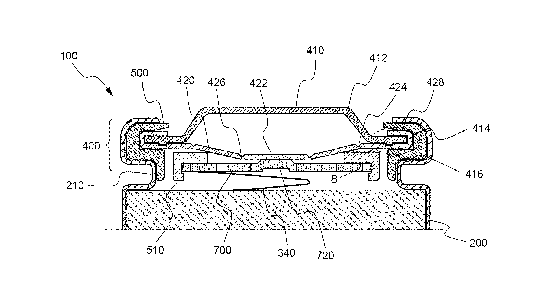
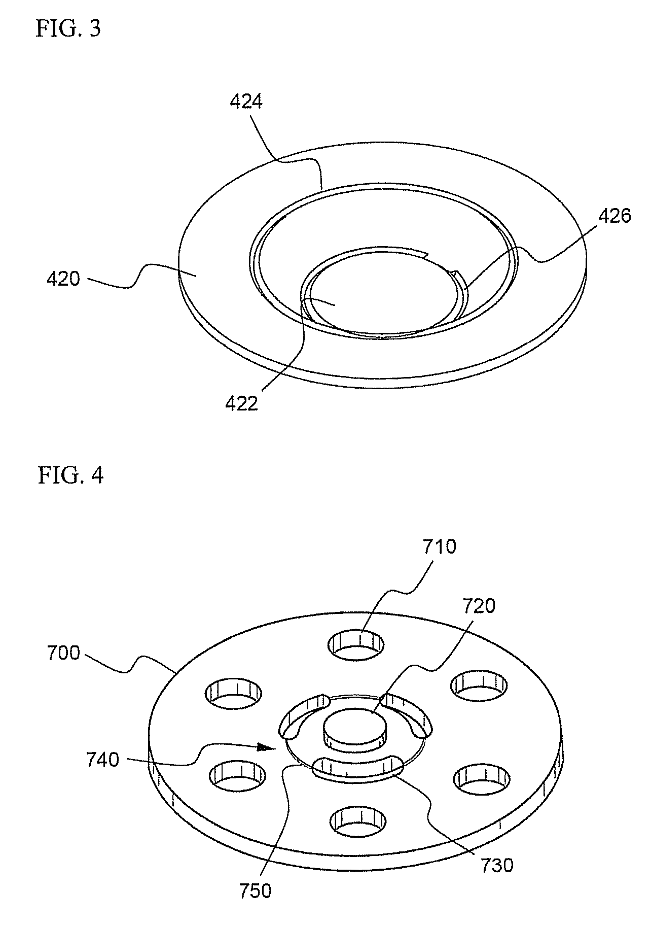
[0061]A top cap was manufactured using a cold rolled carbon steel sheet (SPCE) coated with Ni, and a vent having the structure shown in FIG. 3 and a current intercepting member having the structure shown in FIG. 4 were manufactured using an aluminum sheet (Al1050-H24). At the lower end surface of the top cap was continuously formed a groove having a width of 0.6 mm and a height of 0.04 mm in a concentric shape.

[0062]The vent was formed in the shape of a plate member having an outer diameter of 16 mm and a thickness of 0.3 mm. A first notch constituting the upper bent region of the vent was formed with a diameter of 10 mm and a thickness of 0.13 mm, and a second notch constituting the lower bent region of the vent was formed with a diameter of 4 mm and a thickness of 0.09 mm. The current intercepting member was formed in the shape of a plate member having an outer diameter of 11 mm and a thickness of 0.5 mm. Six gas discharging holes having a diameter of 3 mm were radially formed in ...

experimental example 1

[0066]While 10 batteries manufactured as described in Example 1 and 10 batteries manufactured as described in Comparative example 1 were placed upside down, a pressure was applied into the cells to 15 Kgf so as to check whether an electrolyte leaked from the corresponding battery before the current intercepting member was broken. The results are indicated in Table 1.

[0067]

TABLE 1Occurrence ofOccurrence ofleakageOccurrence ofleakage beforesimultaneouslyleakage afterbreakage ofwith breakagebreakage ofcurrentof currentcurrentNonoc-interceptinginterceptinginterceptingcurrencemembermembermemberof leakageExample 10 / 100 / 100 / 1010 / 10Compar-4 / 101 / 102 / 10 3 / 10ativeexample 1

[0068]It can be seen from Table 1 that the electrolyte did not leak from the batteries of Example 1, whereas the electrolyte leaked from the batteries of Comparative example 1 before and after the breakage of the current intercepting member.

experimental example 2

[0069]While 12 batteries manufactured as described in Example 1 were fully charged to 4 A and 4.2 V. The fully charged batteries were put into an octagonal drum, and the batteries were revolved at a speed of 66 rpm for 30 minutes. After that, the impedance of the respective batteries was measured. Under the same conditions, the 12 batteries were revolved for 150 minutes, and then the impedance of the respective batteries was measured. It can be interpreted that, when the increase rate of the impedance after the drum test to the impedance before the drum test is less than 10%, the electrical connection of the batteries is excellent. The experimental results are shown in FIG. 10.

[0070]In addition, 12 batteries manufactured as described in Comparative example 1 were repeatedly tested in the same manner. The experimental results are shown in FIG. 11.

[0071]As can be seen from these drawings, the increase of the impedance of the batteries of Example 1 was very small after the 30-minute dr...


PUM

PropertyMeasurementUnit
angleaaaaaaaaaa
resistanceaaaaaaaaaa

Abstract

Disclosed herein is a cylindrical secondary battery including a cap assembly constructed in a structure in which a vent, which intercepts electric current and discharges pressurized gas when the interior pressure of the battery is increased due to abnormal operation of the battery, is in contact with a top cap having a protruding central part, wherein the end of the vent is bent to surround the outer circumferential surface of the top cap, and a groove for preventing the leakage of an electrolyte and preventing the occurrence of defectiveness of the battery during the assembly of the battery is formed at interfaces between the vent and the top cap such that the groove is arranged in parallel with the outer circumferential surface of the top cap. The secondary battery according to the present invention has the effect of accomplishing high charging and discharging rate, providing uniform output even when external physical impacts, such as vibration or dropping, are applied to the secondary battery, and preventing the occurrence of defectiveness during the assembly of the secondary battery. Furthermore, the leakage of the electrolyte out of the battery is restrained under these conditions. Consequently, the secondary battery according to the present invention can be preferably used as a high-output power source.

Description

FIELD OF THE INVENTION[0001]The present invention relates to a cylindrical secondary battery having high charging and discharging rate, and, more particularly, to a cylindrical secondary battery including a cap assembly constructed in a structure in which a vent, which intercepts electric current and discharges pressurized gas when the interior pressure of the battery is increased due to abnormal operation of the battery, is in contact with a top cap having a protruding central part, wherein the end of the vent is bent to surround the outer circumferential surface of the top cap, and a groove is formed at interfaces between the vent and the top cap for preventing the leakage of an electrolyte and preventing the occurrence of defectiveness of the battery during the assembly of the battery, thereby accomplishing stable electrical connection between the vent and the top cap, providing instantaneously high output, providing stable output even when external impacts, such as vibration, ar...

Claims


Application Information

Patent Timeline
Patent Type & Authority Patents(United States)
IPC IPC(8): H01M2/12H01M2/08H01M50/169H01M50/574
CPCH01M2/0413H01M2/34H01M2/1241H01M2200/106Y02E60/10H01M50/171H01M50/3425Y02P70/50H01M50/169H01M50/574H01M50/30H01M50/20
Inventor KIM, SUNGJONGLEE, JI HYUNLEE, SANGMINHBYUN, HOKYUNGSEO, GEUN HO
Owner LG ENERGY SOLUTION LTD
Why Eureka
Try Eureka