Electrolytic Hydrogen Generator and Method

a hydrogen generator and electrolysis technology, applied in the field of electrolysis, can solve the problems of difficult to achieve low resistance, and achieve the effects of less voltage, low resistance, and reduced current flow

Inactive Publication Date: 2017-02-02
TURGEON LUKE J
View PDF1 Cites 3 Cited by
  • Summary
  • Abstract
  • Description
  • Claims
  • Application Information

AI Technical Summary

Benefits of technology

[0025]The invention provides that the electrodes are composed of a material having relatively good conductivity, such as copper or brass, that pass through relatively small perforations through the case below the level of the electrolyte. Each electrode is in threaded engagement with a stainless steel support plate located inside the case. The leakage of electrolyte through the perforations, and contact between the electrolyte and the copper or brass electrode, is prevented by non-conductive bushings located on the inside of the case and compressed between the stainless steel support plate and the case. Tension applied to the electrode, as by a nut located on the outside of the case and electrically insulated from the case, compresses the non-conductive bushing between the stainless steel support plate and the case, clamping the support plate to the case and preventing leakage of electrolyte through the perforation. Sealing of the non-conductive bushing may be augmented by O-rings or gaskets disposed on either side of the non-conductive bushing. The non-conductive bushing is selected to be large enough so that the stainless steel support plate is securely supported within the case and securely attached to the case.
[0055]If a bubble of HHO grows on the surface of a core plate, but does not separate from that surface, the location on the core plate in contact with the bubble is not in contact with the electrolyte and is not available to generate more HHO. The Inventors have discovered that increasing the surface area of a plate by texturing the surface of the plate both increases the area for the formation of HHO bubbles and also reduces the tendency of the HHO bubble to adhere to the surface. Texturing of the core plate surface by sanding the surface so that the scratches caused by the sanding process are vertical (and hence parallel to the direction of HHO flow through the electrolyte), improves both HHO bubble formation and release by the bubble from the surface of the plate.

Problems solved by technology

The problem of achieving low resistance is made more difficult by the corrosive nature of the liquid electrolyte within the HHO generator, by the need to seal the generator case against leakage of the electrolyte and of hydrogen gas under pressure, by the need to accommodate possible detonation of the HHO mixture within the generator case, and by the environmental conditions that exist in a motor vehicle or other application.

Method used


Image

  • Electrolytic Hydrogen Generator and Method
  • Electrolytic Hydrogen Generator and Method
  • Electrolytic Hydrogen Generator and Method

Examples


case 6

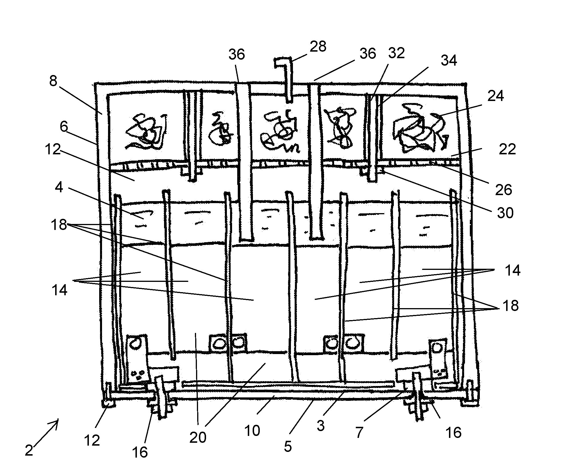
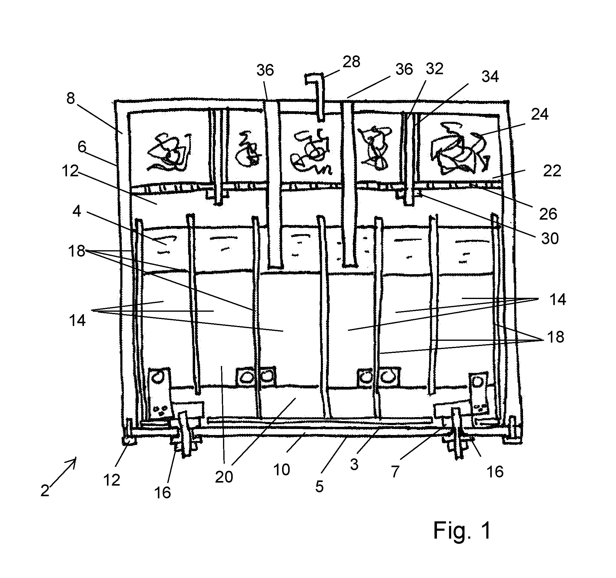
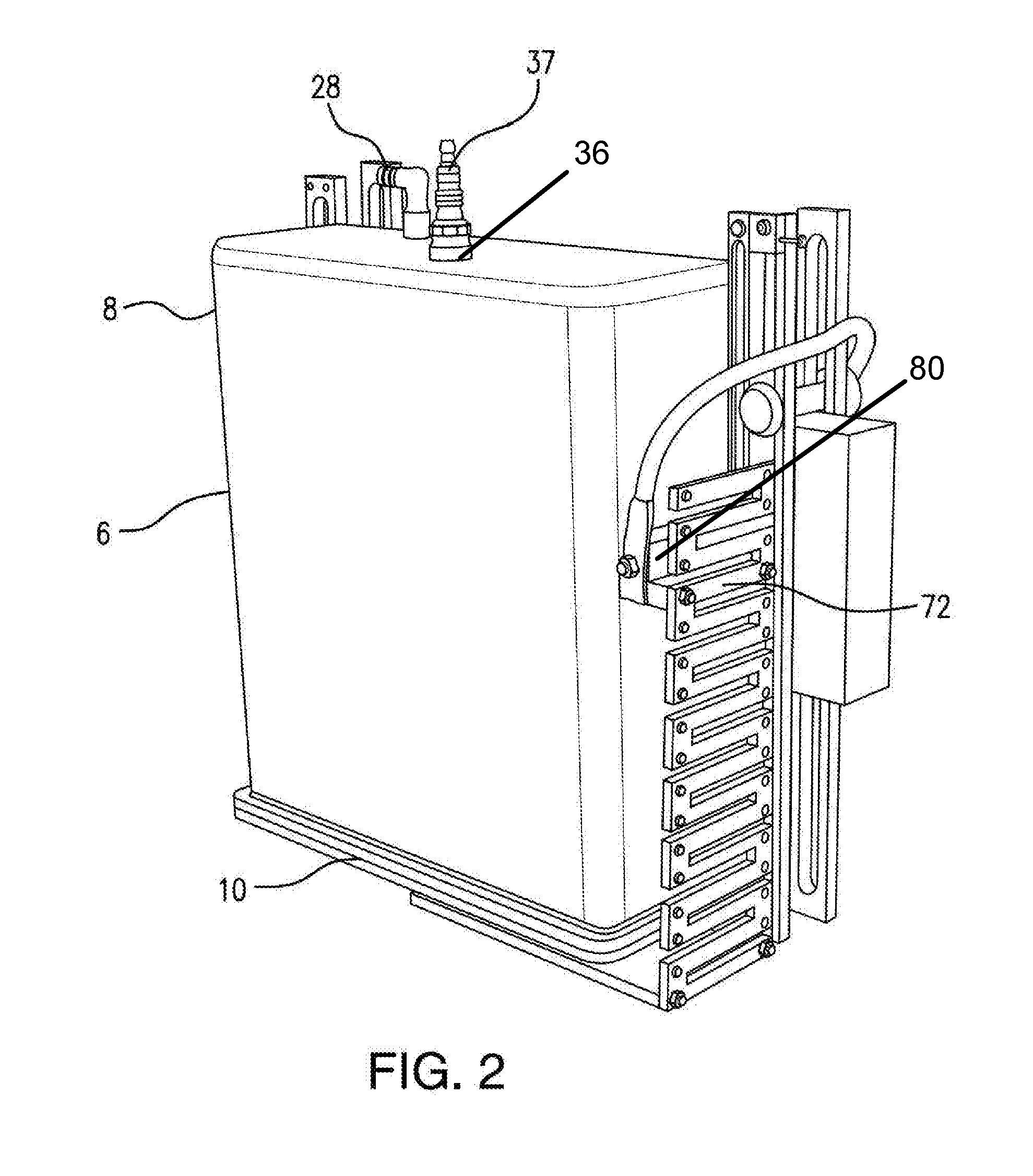
[0157]Electrolytic hydrogen generator 2 or HHO generator 2[0158]Inside 3[0159]Electrolyte 4[0160]Outside 5[0161]Case 6[0162]First and second electrode penetrations 7[0163]Body 8[0164]Interior volume 9[0165]Lid 10[0166]Bolts 11[0167]Hydrogen gas 12[0168]Cores 14[0169]Electrode assembly 16[0170]Plastic plates 18[0171]Chamber 20[0172]Separator plate 22[0173]Stainless steel wool 24[0174]Perforations 26[0175]Nuts 30[0176]Studs 32[0177]Stand-offs 34[0178]Penetrations 36[0179]First and second sets of core plates 38[0180]First and second core connector 40[0181]First and second elongated core fastener (bolt) 42[0182]A corner, a first corner 43[0183]First and second washers 44[0184]An opposing corner, a second corner 45[0185]A clearance cutout 46[0186]A core perforation 47[0187]Non-conducting core plate connector 48[0188]Non-conducting nut 50[0189]A connecting hole 51[0190]Non-conducting spacer 52[0191]Three-dimensional rectangular shape 53[0192]Electrical current flow 54[0193]HHO 56[0194]A f...


PUM

PropertyMeasurementUnit
resistanceaaaaaaaaaa
DC voltageaaaaaaaaaa
voltageaaaaaaaaaa

Abstract

An electrolytic generator to produce a stoichiometric mixture of hydrogen gas and oxygen gas features a case penetration. An electrode extends through the case penetration and clamps a support plate to the inside of the case. The electrode and the support plate are electrically insulated from the case by a non-conducting bushing located within the case and between the support plate and the inside surface of the case. First and second plates are interleaved and maintained in a spaced apart relation along the first and second plate fasteners.

Description

I. RELATED APPLICATIONS[0001]This application claims priority from U.S. Provisional Patent Applications 61 / 433,236 filed Jan. 16, 2011 and 61 / 465,223 filed Mar. 16, 2011, from U.S. non-provisional patent application Ser. No. 13 / 350,221, issued as U.S. Pat. No. 8,852,410 on Oct. 7, 2014, and from U.S. continuation application Ser. No. 14 / 480,906, filed Sep. 9, 2014, all of which are incorporated by reference as if set forth in full herein.II. BACKGROUND OF THE INVENTION[0002]A. Field of the Invention[0003]The Invention relates to the generation of hydrogen through electrolysis. The Invention relates particularly to the on-demand generation of hydrogen for the purpose of improving combustion of fossil fuels such as gasoline or diesel fuel in an internal combustion engine. The invention may be utilized either as a mobile source of hydrogen on a moving motor vehicle or for a stationary engine or for any application where a stoichiometric mixture of hydrogen and oxygen (‘HHO’) is needed,...

Claims


Application Information

Patent Timeline
Patent Type & Authority Applications(United States)
IPC IPC(8): C25B15/02C25B9/06C25B9/20C25B1/08C25B9/17
CPCC25B15/02C25B9/20C25B9/06C25B1/08C25B15/08Y02E60/36C25B1/04C25B9/73C25B9/05C25B9/17
Inventor TURGEON, LUKE J.
Owner TURGEON LUKE J
Why Eureka
Try Eureka