
Driver plate for electromagnetic forming of sheet metal

a technology of electromagnetic forming and drive plate, which is applied in the direction of metal working apparatus, manufacturing tools, and shape safety devices, etc., can solve the problem that the desired sheet metal workpiece may lack suitable electrical conductivity

Active Publication Date: 2009-04-09
THE OHIO STATE UNIV RES FOUND +1
View PDF4 Cites 33 Cited by
  • Summary
  • Abstract
  • Description
  • Claims
  • Application Information

AI Technical Summary

Benefits of technology

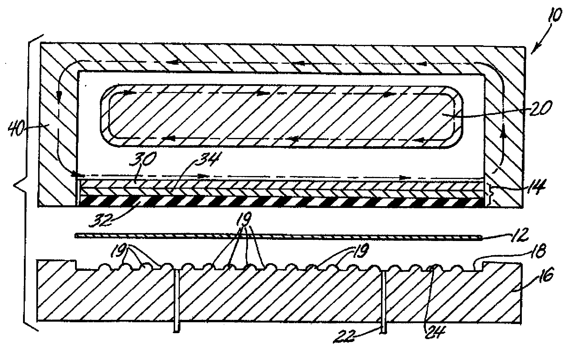
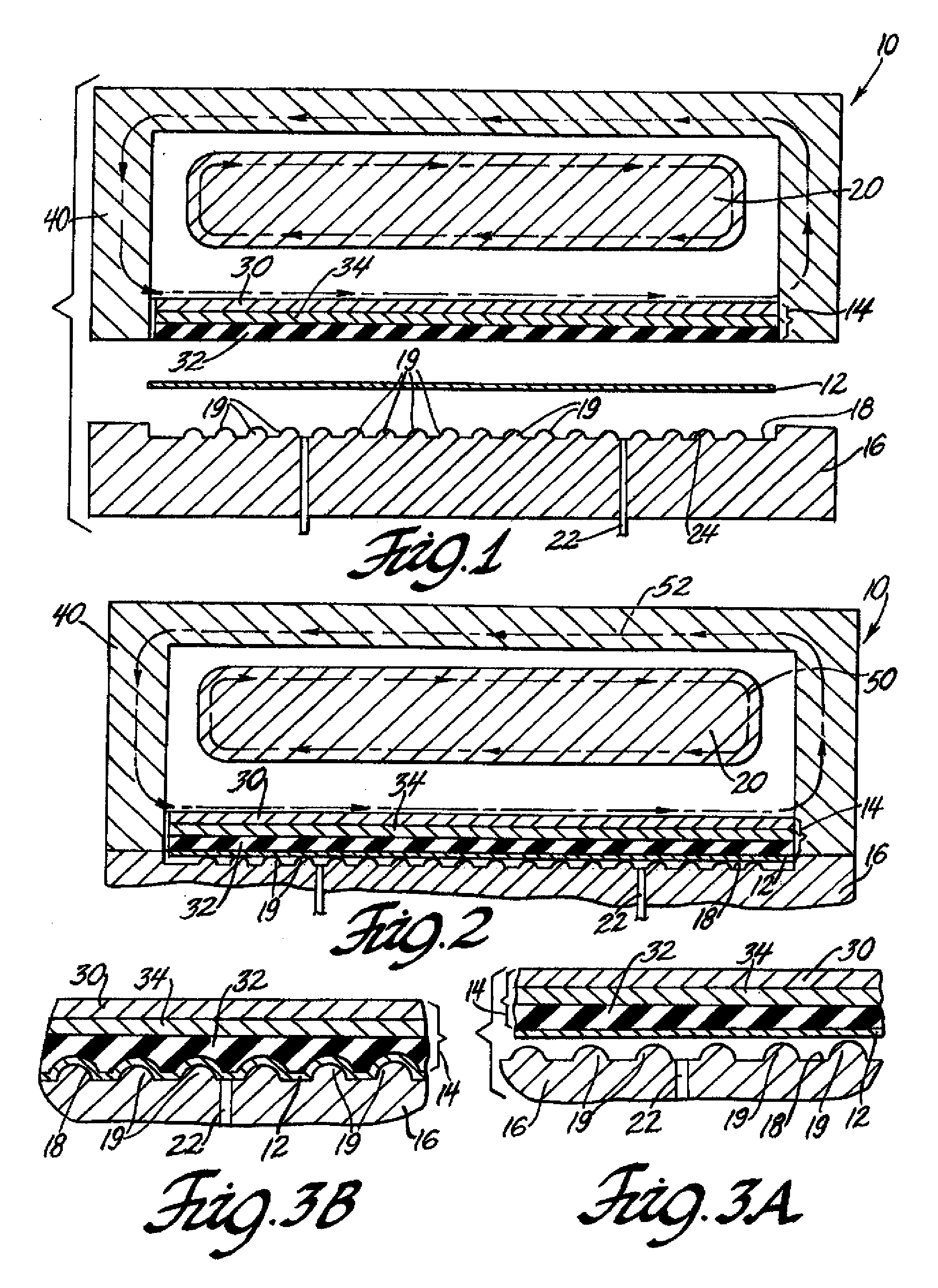
[0008]The multi-layer driver plate has a layer of elastomeric composition and thickness for engaging the surface of the thin sheet metal and driving it against the surface of the forming tool and stretching the metal into conformance with the forming surface. While the thickness of the sheet metal may be about one-half millimeter or less, upstanding or recessed features of the forming surface may have dimensions of a millimeter or more. The workpiece-contacting surface of elastomeric layer of the driver plate accommodates this shaping of the sheet metal by suitably flexing and deforming to push the sheet metal into conformance with the die surface. The thickness of the elastomer layer will usually be greater than the height of elevated or recessed features of the forming surface to flex, deform and force the sheet metal workpiece into and against the metal shaping features of the forming surface. The elastomer layer may be initially flat, or may have the basic contours of the part to be manufactured. This may reduce the strain in the elastomer and increase its lifetime in service. Whether flat or contoured, the ability of the elastomer layer to deform reduces the requirement for precise alignment of the driver plate and forming tool.
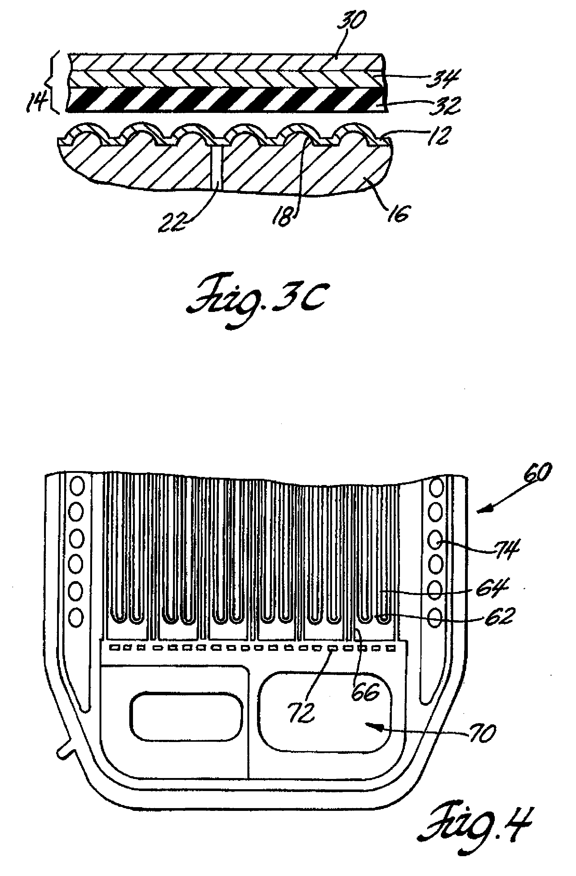
[0010]The driver plate further comprises a low electrical resistivity layer which, preferably, is in the form of a continuous sheet, foil, or film depending on the power requirements of the driver plate. This layer comprises a low resistivity metal such as aluminum, copper, gold, silver, or the like. This low resistivity layer is applied to the exposed side of the rigid layer of the multilayer driver plate and may be less than one millimeter thick in embodiments in which an equally thin (or thinner) sheet metal workpiece is to be formed. In some embodiments the low resistivity layer may be electroplated on the rigid layer. The thickness of this electromagnetically responsive layer may often depend on the thickness and formability of the workpiece because the driving force for the forming operation is electromagnetically induced in this low resistivity layer of the driver plate. Increased thickness and area of the layer (together with lower resistivity) accommodates the creation of a greater force for deformation of the workpiece.
[0014]Thus, the cooperative properties of each layer of the multi-layer configuration allows the driver plate to deform a sheet metal workpiece against a profiled die surface and return to its original pre-forming structure. The ability to participate in electromagnetic sheet metal forming operations without sustaining substantial or permanent disfiguration allows the driver plate to be repeatedly used in high volume EMF forming operations instead of being replaced and recycled after each forming operation.

Problems solved by technology

In some instances, the desired sheet metal workpiece may lack suitable electrical conductivity to respond to the magnetic field and be driven against the forming surface by the discharge of the electromagnetic actuator.

Method used


Image

  • Driver plate for electromagnetic forming of sheet metal
  • Driver plate for electromagnetic forming of sheet metal
  • Driver plate for electromagnetic forming of sheet metal

Examples


Embodiment Construction

[0023]The description of the following embodiment(s) is merely exemplary in nature and is in no way intended to limit the claimed invention, its application, or its uses.

[0024]EMF sheet metal forming techniques are useful in forming thin sheet metal workpieces and may be utilized either alone or in combination with more traditional metal forming techniques, such as stamping. A noted advantage associated with EMF metal forming is its ability to satisfactorily stretch metals at strain rates that would ordinarily cause tearing if performed by a conventional forming process. In fact, EMF can achieve strain rates of up to approximately 105 sec−1 and sheet velocities in the range of 50 to 300 m / s. A single deformation step of a sheet metal workpiece is completed within a few tens of microseconds or so. These capabilities make EMF well suited for shallow forming of thin metal sheets. For example, in one embodiment, an EMF forming operation may be employed to perform one or more steps in th...


PUM

PropertyMeasurementUnit
Depthaaaaaaaaaa
Thicknessaaaaaaaaaa
Strengthaaaaaaaaaa

Abstract

A multi-layer driver plate is disclosed for use in electromagnetic sheet metal forming operations. In one embodiment, the driver plate comprises a first layer characterized by low electrical resistivity and thickness for inducement and application of a suitable electromagnetic forming force, a second layer comprising an elastomeric material for compressing a sheet metal workpiece against a die surface and then regaining its original pre-forming structure, and a third layer interposed between the first layer and the second layer to protect the EMF force providing layer and to provide overall strength and durability to the EMF driver plate.

Description

TECHNICAL FIELD[0001]This invention pertains to electromagnetic forming operations in which a thin sheet metal workpiece is driven at high velocity against a forming surface. More specifically, this invention pertains to the use of a laminated driver plate with an elastomeric layer for contacting the sheet metal and momentarily deforming with it as it is shaped against the forming surface.BACKGROUND OF THE INVENTION[0002]Sheet metal forming processes are known in the art and typically include forcing a sheet metal workpiece against a forming tool surface, sometimes called a die surface. In electromagnetic forming (EMF) of sheet metal the workpiece is rapidly propelled by a momentary electromagnetic force over a short distance against the forming surface at velocities far in excess of those found in a conventional stamping technique. Typically, the movement and deformation of the workpiece is completed within a few tens of microseconds. EMF is usually applied to sheet metal workpiece...

Claims


Application Information

Patent Timeline
IPC IPC(8): B21D26/14B21D26/00
CPCY10T29/49803B21D26/14
Inventor BRADLEY, JOHN R.DAEHN, GLENN S.
Owner THE OHIO STATE UNIV RES FOUND
Learn More