Crank-rocker quick mechanism

A crank-rocker mechanism and crank-rocker technology, which is applied in the direction of prior contact arrangement, power device inside the switch, etc., can solve the problems of increased manufacturing cost, many friction components, mechanical failure, etc., and achieve low mechanical failure rate and manufacturing cost , small resistance, simple structure

Active Publication Date: 2010-11-24
SHANGHAI HUAMING POWER EQUIP CO LTD
View PDF5 Cites 11 Cited by
  • Summary
  • Abstract
  • Description
  • Claims
  • Application Information

AI Technical Summary

Problems solved by technology

[0003] It can be seen from the above diagrams and descriptions that this fast mechanism has a complex structure and many friction components; the structure is complex, it is easy to cause me

Method used


Image

  • Crank-rocker quick mechanism
  • Crank-rocker quick mechanism
  • Crank-rocker quick mechanism

Examples


Embodiment 1

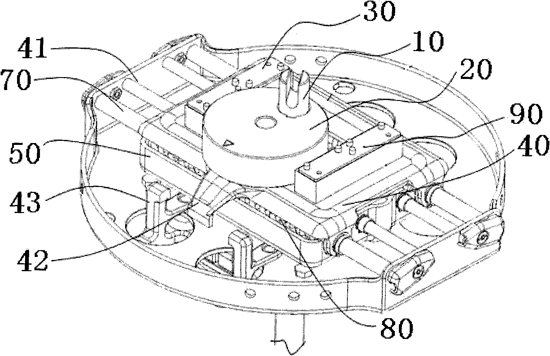
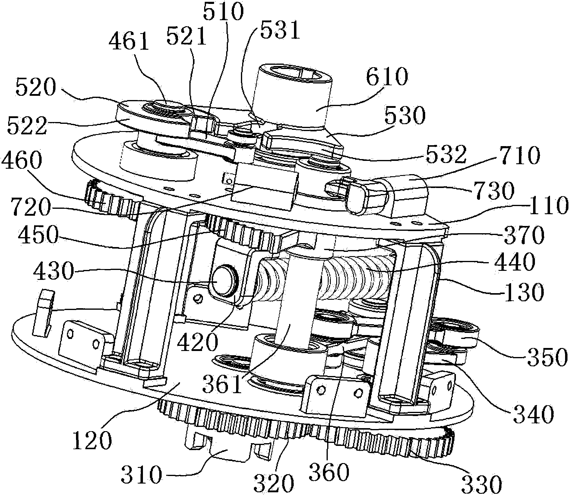
[0069] see image 3 , the crank-rocker fast mechanism shown includes upper and lower mounting plates 110, 120 for installation. The shapes of the upper and lower mounting plates 110, 120 can be designed according to the requirements of the on-load tap changer. The upper and lower mounting plates 110, 120 are connected by three brackets 130, leaving an installation space for the upper and lower mounting plates 110, 120 to facilitate the installation of various parts.

[0070] The tooth coupling 310 and the driving gear 320 are coaxially installed on the lower mounting plate 120 and are located below the lower mounting plate 120 . The driven gear 330 and the first end of the crank 340 are also coaxially installed on the lower mounting plate 120 , wherein the driven gear 330 is located below the lower mounting plate 120 , and the crank 340 is located above the lower mounting plate 120 .

[0071] The jaw coupling 310 is connected with the output shaft (not shown in the figure) of...

Embodiment 2

[0083] see Figure 12 , the crank-rocker fast mechanism shown includes upper and lower mounting plates 110, 120 for installation. The shapes of the upper and lower mounting plates 110, 120 can be designed according to the requirements of the on-load tap changer. The upper and lower mounting plates 110, 120 are connected by three brackets 130, leaving an installation space for the upper and lower mounting plates 110, 120 to facilitate the installation of various parts.

[0084] The jaw coupling 310 and the driving gear 320 are coaxially installed on the lower mounting plate 120 and are located below the lower mounting plate 120, and the first end of the driven gear 330 and the crank 340 are also coaxially installed on the lower mounting plate 120, wherein the driven gear The gear 330 is located below the lower mounting plate 120 , and the crank 340 is located above the lower mounting plate 120 .

[0085]The jaw coupling 310 is connected with the output shaft (not shown in the ...


PUM


Abstract

The invention discloses a crank-rocker quick mechanism which comprises an upper mounting plate and a lower mounting plate which have installation effect, wherein the upper mounting plate is connected with the lower mounting plate through a support to form a certain installation space; and the lower mounting plate is equipped with a transmission mechanism connected with the output shaft of an electric switching mechanism. The quick mechanism also comprises a groove shifting mechanism and an energy-storage crank-rocker mechanism, wherein the groove shifting mechanism is arranged on the upper mounting plate, and the output end of the groove shifting mechanism is connected with the input end of a transfer switch; the energy-storage crank-rocker mechanism is arranged in the installation space, the input end of the energy-storage crank-rocker mechanism is connected with the output end of the transmission mechanism, and the output end of the energy-storage crank-rocker mechanism is connected with the input end of the groove shifting mechanism; and when the energy-storage crank-rocker mechanism releases energy, the groove shifting mechanism is driven to run, thus further leading the transfer switch to work. Compared with the prior art, the crank-rocker quick mechanism has the remarkable advantages as follows: 1. no sliding friction, small resistance, high transmission efficiency, large rotating torque and capability of being applied to the environment with poor lubricating condition; and 2. simple structure, low mechanical failure rate and low manufacturing cost.

Description

Technical field: [0001] The invention relates to the technical field of high-voltage on-load tap-changers, in particular to a fast mechanism for combined on-load tap-changers, and in particular to a novel crank-rocker type fast mechanism. Background technique: [0002] The quick mechanism used for conventional combination on-load tap-changers for many years is figure 1 , figure 2 A fast mechanism is shown, which is composed of components such as a crank, a slider, an upper and lower box, an energy storage spring, a guide rail, a slide bar, a cam disc, and claws. Its action principle is: the switch electric mechanism drives the shaft 10 to rotate, thereby driving the eccentric wheel 20 to rotate eccentrically with the shaft 10 as the center of rotation, and the eccentric wheel 20 pushes the slider 30 and the upper sliding box 40 to move to one end along the guide rail 41; The box 50 is linked with the cam plate 61, and at this moment, the cam plate 61 is blocked by the cla...

Claims


Application Information

Patent Timeline
IPC IPC(8): H01H3/30H01H1/56
Inventor 肖日明沈旭
Owner SHANGHAI HUAMING POWER EQUIP CO LTD
Why Eureka
Try Eureka