Improved cell box

A battery box and an improved technology, applied in the direction of secondary batteries, battery pack components, circuits, etc., can solve the problems of small battery gap, insufficient ventilation of the box, poor battery heat dissipation effect, etc. The effect of ventilation and heat dissipation, improving safety

Active Publication Date: 2010-11-24
许昌许继电科储能技术有限公司
1 Cites 8 Cited by

AI-Extracted Technical Summary

Problems solved by technology

Lithium-ion batteries generate heat during the charging and discharging process. When the batteries are connected in series and parallel, due to the small gap between the batteries and the insufficient ventilation of the box, there will be a large temperature difference between the cells.
Lithium-ion batteries are greatly affected by temperature. When...

Abstract

The invention relates to an improved cell box which comprises a box body and two cell modules that are arranged at the two opposite sides in the box body, wherein the box body consists of four side plates, a box cover and a box bottom, wherein the two side plates which are parallel to each other are taken as air inlet plates of the cell box, and another side plate which is vertical to the air inlet plates and is further away from the cell modules is taken as an air outlet plate of the cell box; each cell module comprises a battery pack, a baffle and a drainage plate, wherein the baffle is provided with a fan; the air inlet plates are provided with air inlets, and the air outlet plate of the cell box is provided with an air outlet which is provided with an outlet fan and the guide plates; and the guide plates are symmetrically arranged at the two sides of the fan. The cell box leads cold air to be absorbed into the box body through the air inlets by the fan and flow through gaps among batteries by the drainage plates, and the heat of the batteries can be taken away through the outlet fan at the air outlet, so that the structure leads the batteries to work in comparatively consistent environment, thus not only leading the batteries to be consistent and improving the safety when in use, but also prolonging the service life of the cell modules.

Application Domain

Battery isolationSecondary cells

Technology Topic

EngineeringCold air +2

Image

  • Improved cell box
  • Improved cell box
  • Improved cell box

Examples

  • Experimental program(1)

Example Embodiment

[0024] The improved battery box of the present invention will be described in further detail below in conjunction with the accompanying drawings.
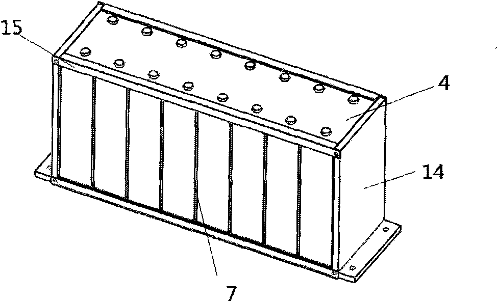
[0025] Such as Image 6 As shown, the improved battery box includes a box body 1 and two battery modules placed in the box body. The two battery modules are arranged on opposite sides of the box body 1 in parallel. Such as Figure 8 As shown, the box body 1 is composed of four side panels, a box cover and a box bottom. Two parallel side panels serve as the air inlet plate 2 of the battery box. The air inlet plate 2 is provided with a plurality of air inlets 10 The area occupied by the air inlet on the air inlet plate is adapted to the width of the battery pack. A side plate perpendicular to the air inlet plate 2 and far from the two battery modules serves as the air outlet plate 3 of the battery box. An air outlet 11 is provided in the middle of the wind plate, an outlet fan 12 is provided inside the air outlet, and a deflector 13 is provided on both sides of the fan, such as Figure 7 As shown, the front end of the deflector is bent inward by 60°. In order to achieve the best heat dissipation effect, it is best to make the height of the deflector equal to the height of the box 1.
[0026] Such as Figure 5 As shown, the battery module includes a battery pack 4, a baffle 5 and a drainage plate 6, such as figure 2 As shown, the battery pack is composed of 8 batteries arranged side by side, such as figure 1 As shown, the battery used in the present invention is a rectangular parallelepiped lithium-ion battery with two poles at the top: a positive pole and a negative pole. There is a gap 7 for ventilation between every two batteries. An L-shaped splint 14 is provided on the left and right sides of the battery pack. Four angle steels 15 are connected between the two splints. The battery pack is connected by the splint and the angle steel. For fixing, the bottom of the clamping plate 14 is provided with bolt holes for connecting the bottom of the box.
[0027] Such as image 3 As shown, the baffle 5 is L-shaped and covers the outside of the battery pack. The two ends of the baffle and the air inlet plate 2 of the box 1 and the side plates parallel to the air outlet plate form two side plates for accommodating the battery pack. In the enclosed space of the air inlet plate 2 and the battery pack 4, there are 9 airflow guide plates 6, such as Figure 4a-Figure 4c As shown, each guide plate 6 is welded by two hard plates (plastic plate or steel plate can be used). The cross section of the guide plate is V-shaped when viewed from the top, and the upper and lower ends of all the guide plates 6 are fixed respectively. A steel plate 17 is connected, and an angle steel II 16 is welded on the outside of the two steel plates 17 respectively. The two ends of the angle steel II 16 are respectively connected to the short side of the baffle and the side plate parallel to the short side. A gap 8 is reserved between them, and the gap corresponds to the gap 7 between the batteries. There are three fans 9 on the long sides of each baffle 5, through which cool air is sucked into the box 1 through the air inlet 10, flows through the guide plate 6 through the gap 7 between the batteries, and passes through the guide plate After being effective enough to stay, the outlet fan 12 at the air outlet 11 quickly takes away the heat generated by the battery. The arrangement of the V-shaped guide plate can make the air intake of the battery gap 7 uniform, and also play a role in accelerating the wind speed and enhancing the cooling effect. In order to ensure the best cooling effect, the height of the two rigid plates of the drainage plate 6 should be equal to or greater than the height of the battery pack 4, and the width of the two rigid plates of the drainage plate 6 should be 20mm-100mm. The angle between the two rigid boards of the board 6 is set to 30°-150°.
[0028] In actual use of the battery box of the present invention, the box cover of the box 1 is first opened, the battery pack 4 is fixed on the bottom of the box 1 through the splint 14, and then the draft plate 6 is fixed to the air inlet 10 and used The gap 8 between the guide plates 6 is aligned with the gap 7 between the batteries, and then the baffle 5 is fixed in the box 1, and a fan 9 is installed on the baffle 5 to align it with the gap 7 between the batteries. Install the deflector 13 and the outlet fan 12 at the air outlet, and finally fix the box cover.
[0029] Finally, it should be noted that the above embodiments are only used to illustrate the technical solutions of the present invention and not to limit it. Although the present invention has been described in detail with reference to the above embodiments, those of ordinary skill in the art should understand that: Modifications or equivalent replacements are made to the specific embodiments of, and any modifications or equivalent replacements that do not depart from the spirit and scope of the present invention shall be covered by the scope of the claims of the present invention.

PUM

PropertyMeasurementUnit
Width>= 20.0mm

Description & Claims & Application Information

We can also present the details of the Description, Claims and Application information to help users get a comprehensive understanding of the technical details of the patent, such as background art, summary of invention, brief description of drawings, description of embodiments, and other original content. On the other hand, users can also determine the specific scope of protection of the technology through the list of claims; as well as understand the changes in the life cycle of the technology with the presentation of the patent timeline. Login to view more.

Similar technology patents

Trusted computing platform chip applicable to mobile communication equipment and authentication method thereof

InactiveCN101986641Aimprove securityachieve security
Owner:HANGZHOU SYNOCHIP DATA SECURITY TECH CO LTD

Hidden frame glass curtain wall structure and method for mounting same

InactiveCN107829513AImprove decorationimprove security
Owner:XINCHANG SICHUANG DESIGN CONSULTING CO LTD

Nano metal silver antibiotic paint and its preparing method

InactiveCN1616559Aimprove security
Owner:RESEARCH INSTITUTE OF TSINGHUA UNIVERSITY IN SHENZHEN

Classification and recommendation of technical efficacy words

  • Good ventilation and heat dissipation
  • improve security

Novel photovoltaic glass window and lighting device

InactiveCN107975335AGood ventilation and heat dissipationhigh degree of shading
Owner:惠州永笙精密模具制品有限公司

Pesticide micro-capsule granules and preparation method thereof

InactiveCN102100229Alow toxicityimprove security
Owner:联合国南通农药剂型开发中心 +1

Method for achieving user authentication by utilizing camera

InactiveCN103678984Aimprove securityGuaranteed picture quality
Owner:湖北微模式科技发展有限公司
Why Eureka
Try Eureka