

Low voltage ride through control circuit of doubly-fed variable-speed constant-frequency wind power generator unit
A technology for wind turbines and low-voltage ride-through, applied in wind power generation, single-network parallel feed arrangements, etc., can solve problems such as limited withstand voltage and overcurrent capacity, deterioration of the power grid, and rise in the voltage of the DC bus of the rotor inverter. To achieve the effect of fast switching action
Active Publication Date: 2010-11-24
天津瑞源电气有限公司
View PDF0 Cites 27 Cited by
- Summary
- Abstract
- Description
- Claims
- Application Information
AI Technical Summary
Problems solved by technology
For doubly-fed variable-speed constant-frequency wind turbines, the doubly-fed generator stator is directly connected to the grid. This special topology enables the frequency converter to only partially control the generator, and the generator stator voltage equation has Under-damping characteristics, in this way, during the instantaneous drop and recovery of the grid voltage, a large electromagnetic transition process will occur inside the doubly-fed motor, and the stator flux linkage cannot quickly follow the sudden change of the stator terminal voltage, resulting in a large transient state Oscillation attenuation component and DC component, due to the decrease of the integral amount, the stator flux linkage speed hardly changes, while the rotor continues to rotate, a large slip will be generated, which will cause overvoltage and overcurrent of the rotor winding, and at the same time The rapid increase of the rotor side current will cause the DC bus voltage of the rotor inverter to increase, and the active and reactive power of the generator will oscillate
Due to the limited withstand voltage and overcurrent capacity of the power device of the frequency converter in the doubly-fed generator set, it is difficult to withstand the severe transition process of the doubly-fed motor when the grid voltage drops
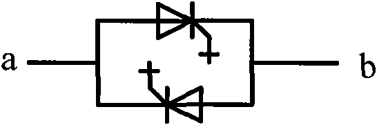
In order to protect the frequency converter and meet the requirements of the power system for low-voltage ride-through of double-fed generators, active or active crowbar protection circuits (crowbar) are mainly used at present. The basic circuit structure is shown in Figure 6. The rotor is equipped with a rotor short-circuit protection circuit controlled by IGBT, GTO and other devices that can be turned off. When the rotor current exceeds a certain set value, the crowbar protection circuit is put into operation, and the rotor inverter is out of operation, providing a bypass for the large current on the rotor side. , to achieve the purpose of limiting the current and protecting the inverter. This kind of protection circuit can basically realize the LVRT operation of the doubly-fed generator set, but it has the following problems: 1. Since the generator stator is still connected to the grid, once the crowbar protection circuit operates, The doubly-fed generator becomes an ordinary asynchronous motor and rotates freely, which will absorb reactive excitation power from the grid, which is not conducive to the recovery of the grid voltage. According to the reactive power-voltage characteristics of the generator, when the machine terminal voltage drops beyond a certain range, the generator will draw The absorbed reactive power increases sharply as the voltage decreases. Since the reactive power characteristics of the system reactive power supply decrease with the voltage decrease, the grid voltage will further drop due to the lack of reactive power in the grid. In severe cases, the voltage may be reduced 2. During the recovery of the power grid, a larger rotor current may appear during the oscillation process, which makes the crowbar protection circuit work again, and absorbs a large amount of reactive power from the power grid, which leads to the aggravation of the power grid oscillation process, which is not conducive to the recovery of the power grid, and even 3. Due to the great difference in the degree of rotor overcurrent under different grid drop conditions, it is difficult to choose a crowbar protection circuit that can prevent DC side overvoltage and effectively suppress rotor side overcurrent. The current limiting resistor
To sum up, the LVRT control circuit of double-fed variable-speed constant-frequency wind turbines generally has problems such as complex control methods, poor reliability, and high cost.
Method used
View moreImage
Smart ImageViewing Examples

Examples
Embodiment Construction
Login to View More PUM
 Abstract
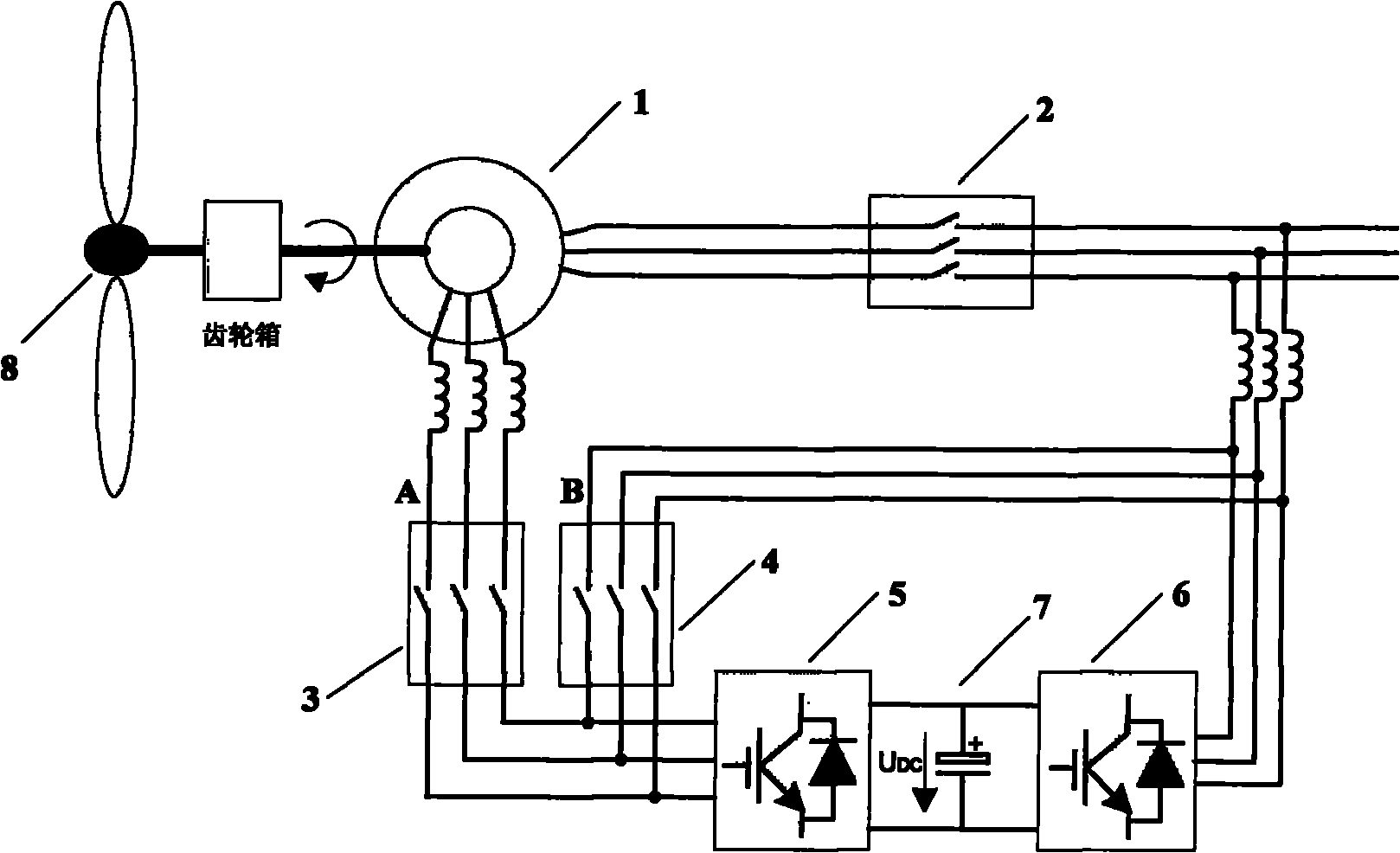
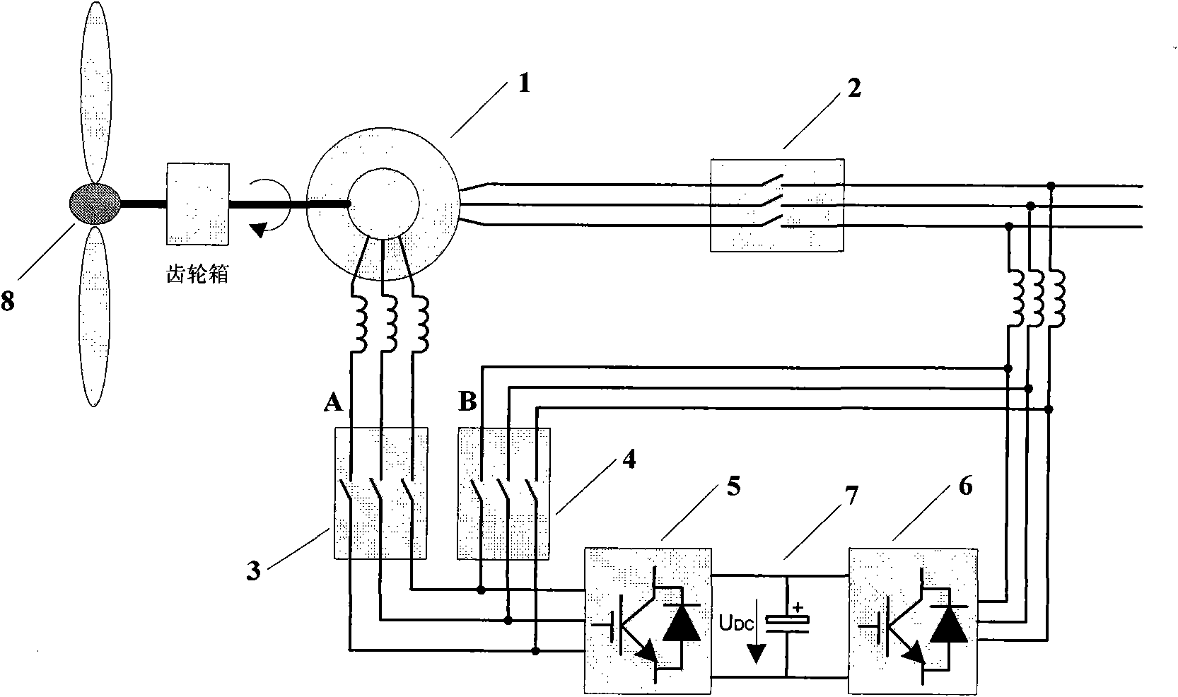
The invention relates to a low voltage ride through control circuit of doubly-fed variable-speed constant-frequency wind power generator unit, which comprises a power grid, a doubly-fed power generator and a doubly-fed frequency converter and which is mainly technically characterized in that: first three-phase alternating current switches are connected in series between stators of the power grid and the doubly-fed power generator, second three-phase alternating current switches are connected in series between a rotor of the doubly-fed power generator and a rotor-side inverter of the doubly-fed frequency converter, and third three-phase alternating current switches are connected in series between the rotor-side inverter of the doubly-fed frequency converter and a grid side inverter of the doubly-fed frequency converter. The low voltage ride through control circuit has the characteristics of reasonable design, great simplicity and stable and reliable performance, guarantees the implementation of low voltage ride through function of doubly-fed power generator unit and safe and stable power grid, reduces the cost thereof, and can be widely applied to the field of wind power generation.
Description
Low voltage ride through control circuit of doubly-fed variable-speed constant-frequency wind turbine generator set technical field The invention belongs to the field of wind power generation, in particular to a low-voltage ride-through control circuit of a double-fed variable-speed constant-frequency wind power generating set. Background technique In recent years, wind power generation has developed rapidly all over the world. With the continuous expansion of installed capacity of wind power generation, the influence of wind power generation system on the power grid is increasing. When the grid voltage drops by a certain value, if a large number of wind turbines cut off the grid, it will cause a large change in the power flow of the system and may even cause a large-scale power outage. Therefore, the traditional method of automatically disconnecting the wind turbines from the grid is no longer suitable for the new grid operation criteria. . In order to keep wind power ge...
Claims
Login to View More Application Information
Patent Timeline
 IPC IPC(8): H02J3/38
CPCY02E10/763Y02E10/76
Inventor周玲玲侯立军孟永庆张新强
Owner天津瑞源电气有限公司