Low-noise, low-power, low drift offset correction in operational and instrumentation amplifiers

A technology of amplifiers and differential amplifiers, applied in the direction of improving amplifiers to reduce noise effects, amplifiers, power amplifiers, etc., can solve problems such as the impact of the total power budget of amplifiers

Active Publication Date: 2010-11-24
NUMBER 14
View PDF3 Cites 20 Cited by
  • Summary
  • Abstract
  • Description
  • Claims
  • Application Information

AI Technical Summary

Problems solved by technology

In many cases, such a large supply current increase would have an

Method used


Image

  • Low-noise, low-power, low drift offset correction in operational and instrumentation amplifiers
  • Low-noise, low-power, low drift offset correction in operational and instrumentation amplifiers
  • Low-noise, low-power, low drift offset correction in operational and instrumentation amplifiers

Examples


Embodiment Construction

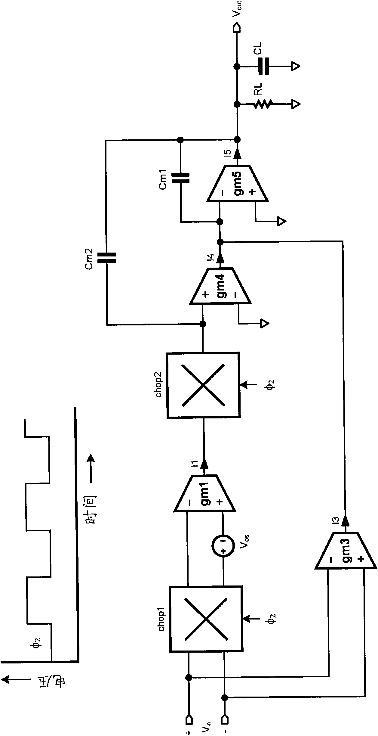
[0064] In the accompanying drawings, for reference, all switches are shown in the state of the corresponding low control signal in the relevant examples. In this regard, the word switch is used here and in the following claims in the sense that it can be singular and plural, includes one or more on / off switches, and alternately connects a line switch to either of the other two lines. However, when used in the plural sense, each such switch responds to the same control signal. Also, the term amplifier is used herein to mean an amplifier having one or more stages, and may include frequency compensation.

[0065] Table 1 summarizes the characteristics of the chopping and auto-zeroing techniques used to reduce the dc offset and 1 / f noise of the amplifier.

[0066]

[0067] Table 1. Characteristics of chopping and auto-zeroing

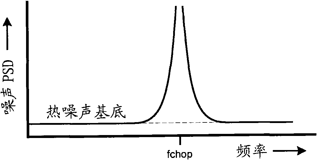
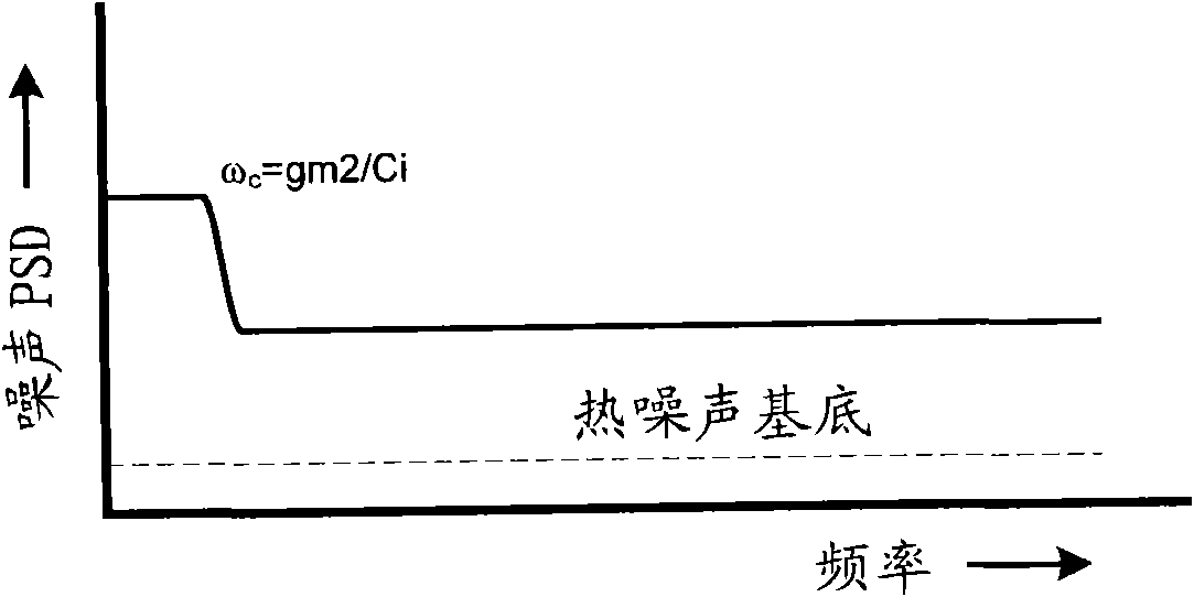
[0068]Obviously, each technology has its own set of advantages and disadvantages. Chopping results in low noise but causes noticeable output ripple,...


PUM


Abstract

Low-noise, low-power, low drift offset correction in operational and instrumentation amplifiers and amplifiers using the same are disclosed. The amplifiers disclosed use different combinations of chopping and auto-zero techniques. Also disclosed are amplifiers using on-off switches to affect the chopping and auto-zeroing, with unique circuits for driving the switches on the differential input to provide boot-strapped switch controls. Other features are disclosed.

Description

technical field [0001] The present invention relates to the field of operational and instrumentation amplifiers. Background technique [0002] A key performance specification for an op amp is its dc error, or offset voltage. Offset voltage limits the amplifier's ability to handle small dc input voltages. The total offset voltage is usually specified as a single error source assumed at the input. The value of this virtual voltage source represents the input referred offset voltage of the amplifier. The significance of this parameter lies in the fact that the amplifier will not be able to handle any dc voltage on its input that is less than the input reference offset voltage. [0003] In monolithically integrated operational amplifiers, the input-referred offset voltage (also known as input offset, offset voltage, or simply offset) is primarily due to statistical mismatch between critical components in the circuit. Typically, these critical components include input-stage t...

Claims


Application Information

Patent Timeline
IPC IPC(8): H03F1/26H03F3/20
CPCH03F2203/45212H03F3/45475H03F2203/45138H03F2200/261H03F3/347H03F3/45968
Inventor R·G·H·埃斯豪齐尔N·范里恩
Owner NUMBER 14
Why Eureka
Try Eureka