
Deformation ellipse-circular gear back planting rotating type transplanting mechanism of walking transplanter

A technology of deforming elliptical gears and cylindrical gears, which is applied in the direction of belts/chains/gears, transplanting machinery, mechanical equipment, etc. It can solve the problems affecting the upright growth of seedlings, the small adjustable range of transmission ratio, and the large inclination of seedlings, etc., to achieve Light weight, meet the requirements of transplanting rice seedlings, low rate of floating seedlings and inverted seedlings

Inactive Publication Date: 2010-12-01
ZHEJIANG SCI-TECH UNIV
View PDF4 Cites 6 Cited by
  • Summary
  • Abstract
  • Description
  • Claims
  • Application Information

AI Technical Summary

Problems solved by technology

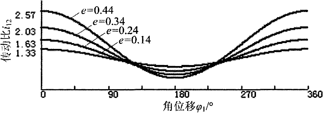
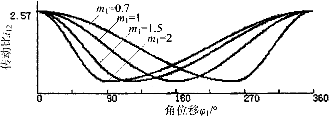
Rotary splitting mechanisms mainly include eccentric non-circular gear transmission, elliptical gear transmission, etc., but the pitch curves of the driving wheels (eccentric cylindrical gear, elliptical gear) are all symmetrical about the x-axis, and the transmission ratio can only be adjusted by adjusting the eccentricity. Longitudinal change, once the eccentricity or eccentricity is determined, the periodic change law of its transmission ratio is also determined (only symmetrically distributed), and the adjustable range of its transmission ratio is small, so it is used as a rotary inserting mechanism for transmission components. The static trajectory formed is generally a "dolphin-shaped" curve, and the opening of the transplanting hole is not very small, which sometimes causes a large inclination of the transplanted seedlings, which affects the upright growth of the seedlings

Method used


Image

  • Deformation ellipse-circular gear back planting rotating type transplanting mechanism of walking transplanter
  • Deformation ellipse-circular gear back planting rotating type transplanting mechanism of walking transplanter
  • Deformation ellipse-circular gear back planting rotating type transplanting mechanism of walking transplanter

Examples


Embodiment Construction

[0018] The present invention will be further described below in conjunction with drawings and embodiments.

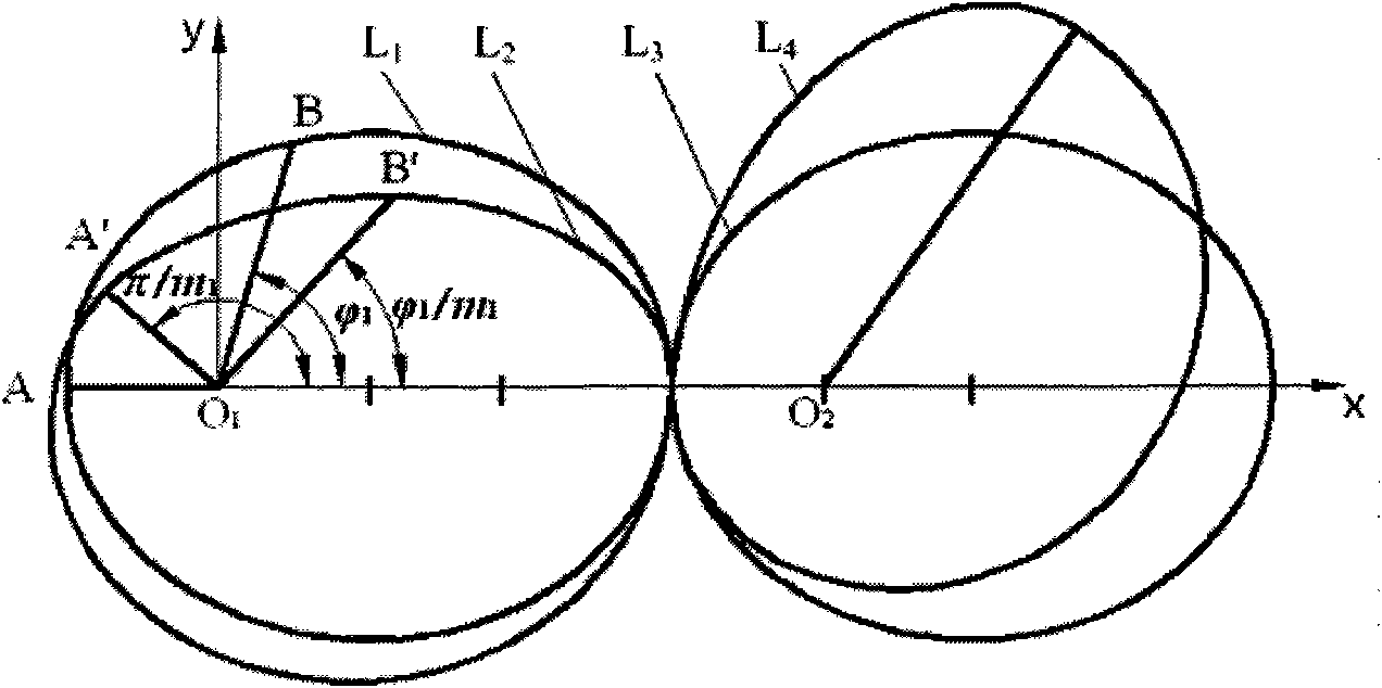
[0019] A deformed ellipse can be thought of as a deformation of an ellipse. When deforming, the length of the radial direction remains unchanged, while the corresponding polar angle shrinks m in the upper half of the ellipse 1 times, shrink m in the lower half of the ellipse 2 times. (like figure 1 Shown, L 1 : Ellipse, L 2 : deformed ellipse, L 3 : conjugate ellipse, L 4 : conjugate deformed ellipse) O 1 A, O 1 B is the radial direction of the ellipse, and the corresponding polar angles are π, shrink m 1 After doubling, the radial direction O of the deformed ellipse is obtained 1 A', O 1 B', and its corresponding polar angle is π / m 1 , Deformed Ellipse L 2 The equation for:

[0020] ( In 0~π / m 1 between) (1)

[0021] ( in π / m 1 ~2π) (2)

[0022] To ensure that the two curves of the deformed ellipse are closed, m 1 and m 2 The following r...


PUM


Abstract

The invention discloses a deformation ellipse-circular gear back planting rotating type transplanting mechanism of a walking transplanter. A left and a right gear boxes with the same internal structure are respectively fixed on the shaft ends extending outside a chain wheel box from a center shaft, wherein center deformation ellipse gears fixed on the chain wheel box through a left and a right flanges are respectively arranged on both ends of the center shaft in the gear boxes; the left and the right center deformation ellipse gears drive middle circular gears fixed with the left and the right middle deformation ellipse gears on a left and a right middle shafts to rotate through the left and the right middle deformation ellipse gears fixedly arranged on the left and the right middle shafts; the left and the right circular gears are engaged with a left and a right planet circular gears fixedly arranged on a left and a right planet shafts; and planting arm parts are fixed on one ends of the left and the right planet shafts extending from the gear box. Only one set of planet gears in the gear boxes are used for transmission relative to the center deformation ellipse gears to drive one planting arm to move. The mechanism has a buckle-shaped track to have a small planting pit so as to meet the requirement for rice planting.

Description

technical field [0001] The invention relates to agricultural machinery, in particular to a deformed ellipse-cylindrical gear rear-inserting rotary splitting mechanism of a walking rice transplanter. Background technique [0002] At present, there are mainly two kinds of planting mechanism forms for walking rice transplanters sold on the market: crank rocker type sub-insertion mechanism and rotary type sub-insertion mechanism. Compared with the crank and rocker type, the rotary type insertion mechanism has the advantages of small inertial force, small vibration and good stability. Rotary splitting mechanisms mainly include eccentric non-circular gear transmission, elliptical gear transmission, etc., but the pitch curves of the driving wheels (eccentric cylindrical gear, elliptical gear) are all symmetrical about the x-axis, and the transmission ratio can only be adjusted by adjusting the eccentricity. Longitudinal change, once the eccentricity or eccentricity is determined, ...

Claims


Application Information

Patent Timeline
Patent Type & Authority Applications(China)
IPC IPC(8): A01C11/02F16H37/02
Inventor 赵匀黄巨明高林弟原新斌
Owner ZHEJIANG SCI-TECH UNIV
Learn More