Portable electronic device
An electronic device, portable technology, applied in the direction of electrical equipment shell/cabinet/drawer, electrical components, electrical equipment structural parts, etc., can solve problems such as loss and detachment of protective cover
- Summary
- Abstract
- Description
- Claims
- Application Information
AI Technical Summary
Problems solved by technology
Method used
Image

Examples
no. 1 example
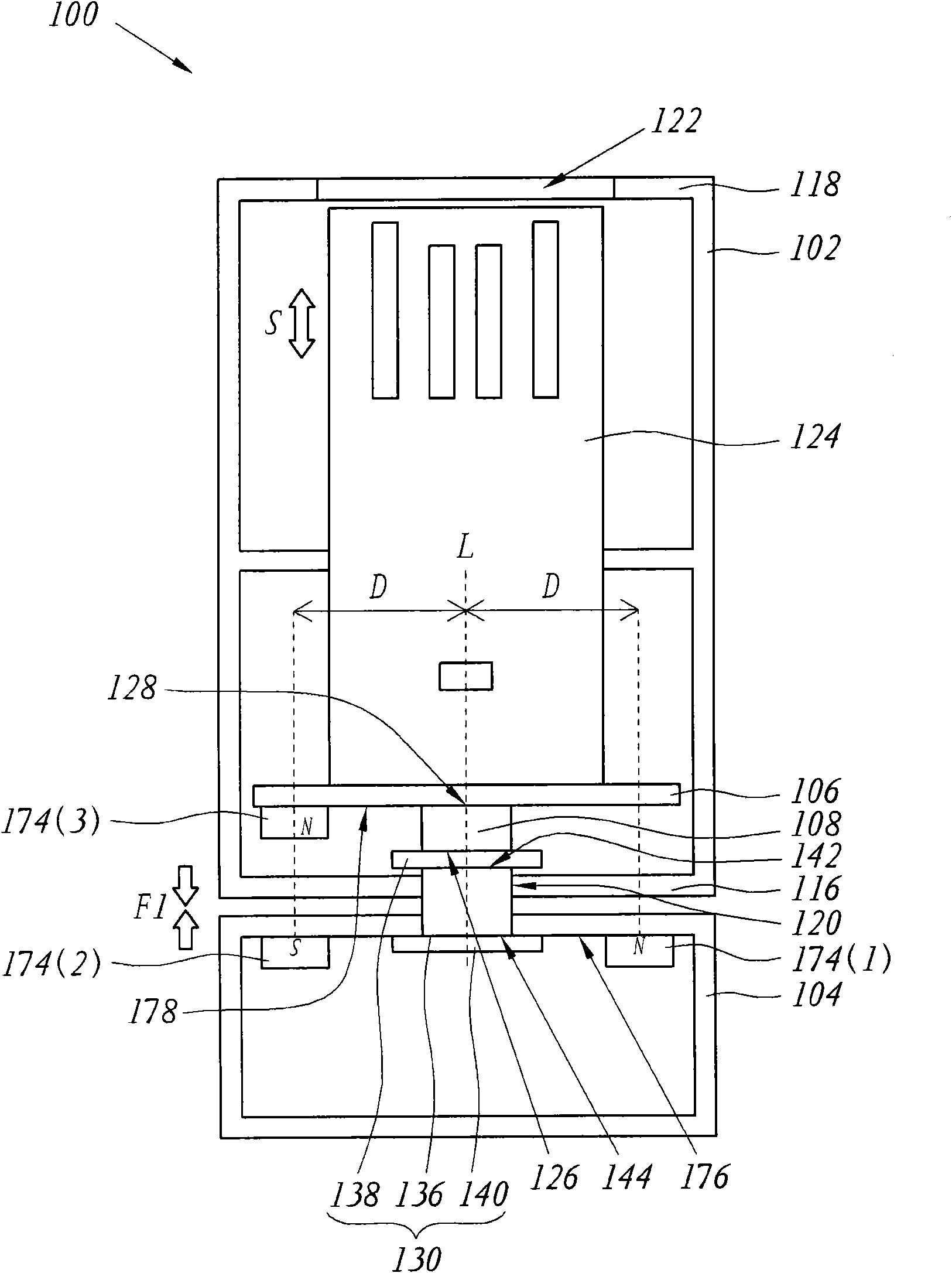
[0022] Please refer to figure 1 , which is an internal perspective view of the portable electronic device according to the first embodiment of the present invention. Here, the portable electronic device is illustrated by taking a common electronic storage device—a memory disk (memory disk) as an example. Such as figure 1 As shown, the flash drive 100 includes a casing 102 , a rotating part 104 (rotating part), a pivot unit 130 , a magnet set 174 and a connecting rod 108 . The housing 102 includes a base 106 and an electronic component 124 . Wherein, the magnet set 174 includes a first magnet 174(1), a second magnet 174(2) and a third magnet 174(3). The rotating element 104 is connected to the casing 102 through the pivot unit 130 , so that the casing 102 and the rotating element 104 are rotatably connected to each other without being separated. The connecting rod 108 connects the pivot unit 130 and the carrier 106 .
[0023] The electronic component 124 is located on the ...
no. 2 example
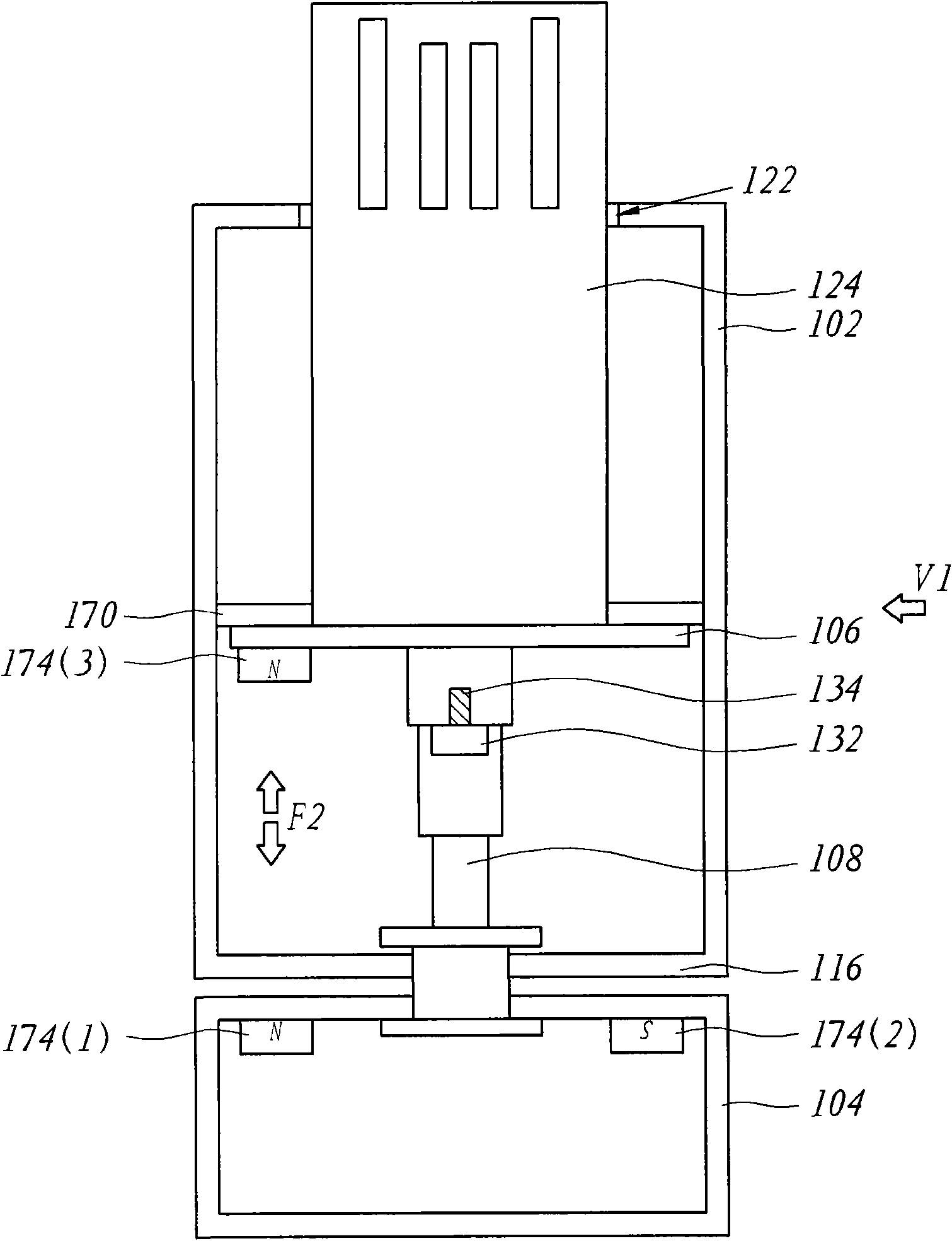
[0038] Please refer to Image 6 , which is an internal perspective view of the flash drive according to the second embodiment of the present invention. The second embodiment follows the element numbers of the first embodiment. Wherein, the difference between the second embodiment and the first embodiment is that the first magnet 114 (1) and the second magnet 114 (2) are arranged on the carrier 106 in the flash drive 200 of the second embodiment, and the third The magnet 114 ( 3 ) is disposed inside the rotating element 104 . Furthermore, in the second embodiment, the first magnet 114 ( 1 ) and the second magnet 114 ( 2 ) are disposed on the surface 178 of the carrier 106 facing the rotating element 104 . The third magnet 114 ( 3 ) is disposed on the inner surface 176 of the rotating element 104 adjacent to the casing 102 .
[0039] Such as Image 6 As shown, the first magnet 114(1) and the second magnet 114(2) are at the same distance D from the rotation axis L, and the co...
no. 3 example
[0042] Please refer to Figure 8 , which is an internal perspective view of the flash drive according to the third embodiment of the present invention. Part numbering of the elements of the third embodiment follows the numbering of the elements of the first embodiment. Wherein, the difference between the third embodiment and the first embodiment is that the first magnet 110(1) and the second magnet 110(2) of the flash drive 300 are arranged on the inner wall surface 146 of the second side wall 116, and the second The three magnets 110 ( 3 ) are disposed on the base 302 , and the third magnet 110 ( 3 ) is disposed on a surface of the base 302 facing the inner wall surface 146 . In particular, the second end 306 of the connecting rod 304 in this embodiment is fixedly connected to the carrier 302 . In addition, the flash drive 300 includes a third stopper 308 and a fourth stopper 310 , the third stopper 308 is fixed on the housing 314 and has a third slope 312 , the fourth stop...
PUM
 Abstract
Description
Claims
Application Information
 - R&D Engineer
- R&D Manager
- IP Professional
- Industry Leading Data Capabilities
- Powerful AI technology
- Patent DNA Extraction
Browse by: Latest US Patents, China's latest patents, Technical Efficacy Thesaurus, Application Domain, Technology Topic.
© 2024 PatSnap. All rights reserved.Legal|Privacy policy|Modern Slavery Act Transparency Statement|Sitemap