Magnetic latching relay capable of resisting short-circuit current

A technology of magnetic latching relays and short-circuit currents, applied in electromagnetic relays, electromagnetic relay details, relays, etc., can solve the problems of unsatisfactory closing pressure and increased product cost, and achieve no sudden change in contact pressure, short circuit time, and contact pressure The effect of a steady rise

Inactive Publication Date: 2017-03-15
XIAMEN HONGFA ELECTRIC POWER CONTROLS
View PDF13 Cites 21 Cited by
  • Summary
  • Abstract
  • Description
  • Claims
  • Application Information

AI Technical Summary

Problems solved by technology

Regardless of the type, double the short-circuit current is used to flow through the movable reed (that is, the movable reed) and the movable reed lead-out piece (that is, the movable reed lead-out piece), and in the movable reed (that is, the movable reed lead-out piece). The electromagnetic force generated on the reed) resists the electric ...

Method used


Image

  • Magnetic latching relay capable of resisting short-circuit current
  • Magnetic latching relay capable of resisting short-circuit current
  • Magnetic latching relay capable of resisting short-circuit current

Examples


Embodiment 1

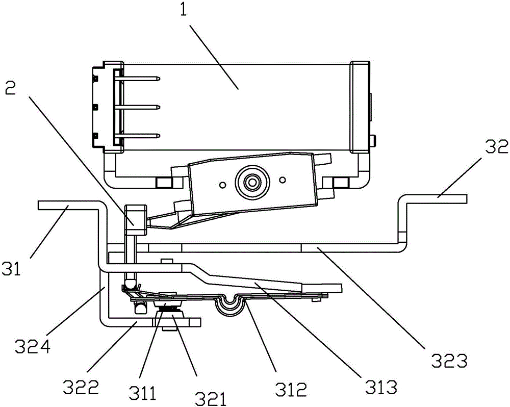
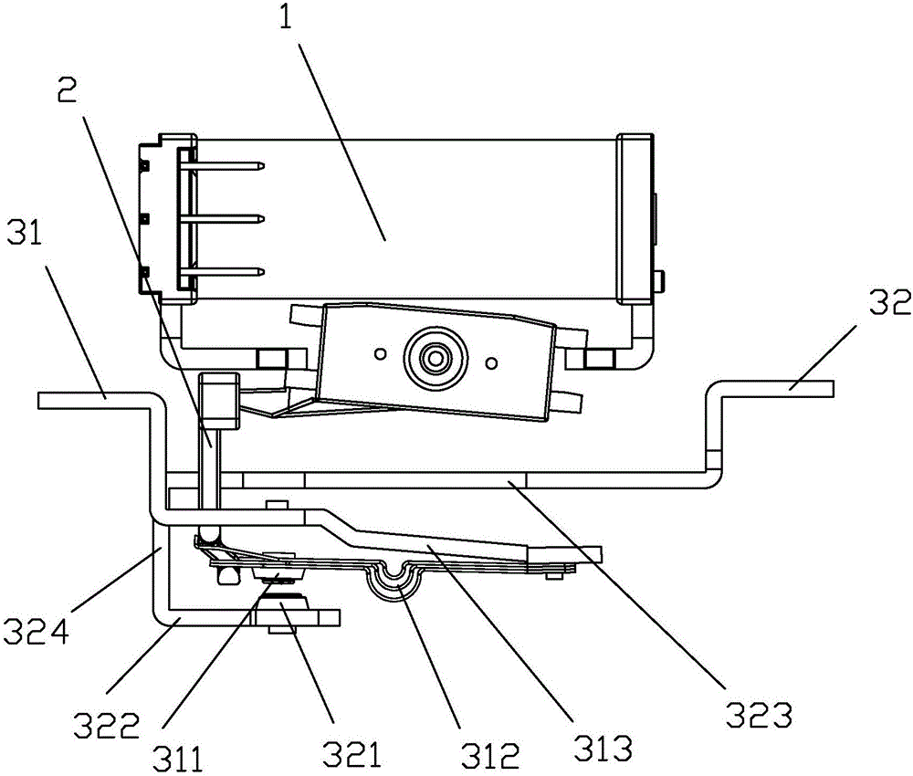
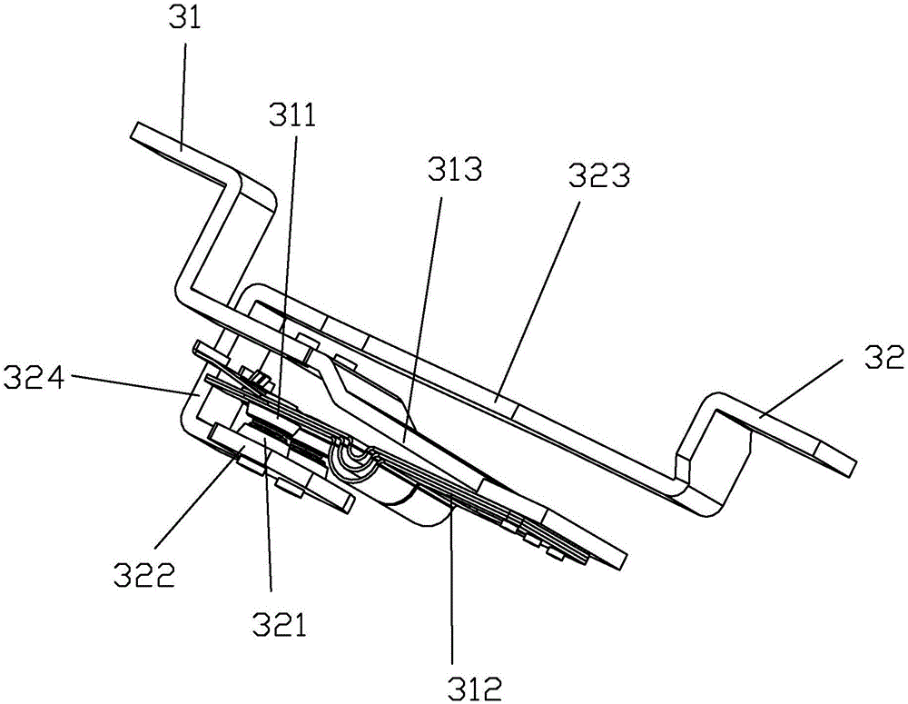
[0068] see Figure 1 to Figure 3 As shown, a magnetic latching relay capable of resisting short-circuit current of the present invention includes a magnetic circuit system 1, a contact system and a push mechanism 2, and the push mechanism 2 is connected between the magnetic circuit system 1 and the contact system; the contact The system includes a moving spring part and a static spring part; in this embodiment, the contact system is a group, including a set of moving spring parts and static spring parts that cooperate, that is, a moving spring part 31 and a static spring part 32, the The moving spring part 31 comprises a moving contact 311, a moving reed 312 and a moving spring lead-out piece 313, one end of the moving reed 312 is connected to the moving contact 311, and the other end of the moving reed 312 is connected to an end of the moving spring leading-out piece 313, The spring lead-out piece 313 is arranged on the thickness direction of the movable reed 312 and is away ...

Embodiment 2

[0092] see Figure 10 As shown, a magnetic latching relay capable of resisting short-circuit current of the present invention differs from Embodiment 1 in that the structure of the connecting piece 324 is different. In this embodiment, the connecting piece 324 is U-shaped, and the connecting piece 324 One side of the head of the driven reed 312 bypasses the head of the movable reed 312 and is connected between the static spring 322 and the lead-out piece 323 of the static spring.

Embodiment 3

[0094] see Figure 11 As shown, a magnetic latching relay capable of resisting short-circuit current of the present invention differs from Embodiment 1 in that the structure of the connecting piece 324 is different. In this embodiment, the connecting piece 324 is U-shaped, and the connecting piece 324 The other side of the head of the driven reed 312 bypasses the head of the movable reed 312 and is connected between the static spring 322 and the static spring lead-out piece 323 .


PUM


Abstract

The invention discloses a magnetic latching relay capable of resisting a short-circuit current. The magnetic latching relay comprises a magnetic circuit system, a contact system and a push mechanism, wherein a movable spring part comprises a movable contact, a movable spring plate and a movable spring lead-out plate; the movable spring lead-out plate is arranged at one side, departing from the moving contact, in the thickness direction of the movable spring plate; a fixed spring part comprises a fixed contact, a fixed spring plate and a fixed spring lead-out plate; the fixed spring lead-out plate also is arranged at one side, departing from the moving contact, in the thickness direction of the movable spring plate, so that the direction of current flowing through the movable spring lead-out plate is opposite to that of the current flowing through the movable spring plate. According to the magnetic latching relay, the electro-dynamic repulsion force generated by single short-circuit current between the movable contact and the fixed contact can be resisted by electromagnetic repulsion force generated by formed double short-circuit current on the movable spring plate on the basis of not increasing the overall dimension of a product or not increasing the power consumption of a coil control part, so that the closing pressure of the movable contact and the fixed contact is greatly improved, the short-circuit current is resisted and the requirements of the product on simple, compact and small structures are met.

Description

technical field [0001] The invention relates to a magnetic latching relay, in particular to a magnetic latching relay capable of resisting short-circuit current. Background technique [0002] The structure of the existing magnetic latching relay consists of a magnetic circuit system, a contact system, a driving mechanism and a base. The magnetic circuit system generally consists of two basically symmetrical magnetic circuits, including stationary magnetizer parts, movable magnetizer parts and coils. The contact system includes a moving spring part and a static spring part. The pushing mechanism is generally acted by a pushing block. Between the movable magnet guide part and the moving spring part. The relay coil passes the positive pulse voltage, the magnetic circuit system works, the pushing block pushes the moving spring part, making the contacts contact, the relay operates, the coil passes the reverse pulse voltage, the magnetic circuit system works, the pushing block pu...

Claims


Application Information

Patent Timeline
IPC IPC(8): H01H51/01H01H50/58
CPCH01H50/58H01H51/01
Inventor 钟叔明代文广廖国进
Owner XIAMEN HONGFA ELECTRIC POWER CONTROLS
Why Eureka
Try Eureka