Bell-type nozzle blow-molding installation

a technology of blow molding and nozzles, which is applied in the field of bell-type nozzle blow molding installation, can solve the problems of increased weight, increased operating speed, and increased weight of moving parts, and achieves the effects of less constraint, reduced wear due, and smoother and longer-lasting

Inactive Publication Date: 2007-01-23
SIDEL PARTICIPATIONS SAS
View PDF9 Cites 23 Cited by
  • Summary
  • Abstract
  • Description
  • Claims
  • Application Information

AI Technical Summary

Benefits of technology

[0008]By means of the provisions specific to the invention, it is only between the co-operating elements (wall of the mold / nozzle) that the securing force is exerted, and said elements are attracted towards each other by implementing suitable means. In such an arrangement, the respective supports for supporting the mold and for supporting the nozzle are no longer subjected to high reaction forces as they are in prior devices. Since they only have to perform their support functions, the respective supports for the mold and for the nozzle need to be dimensioned only for performing said support functions: they can thus be made in forms that are lighter in weight than the prior structures, thereby reducing their weights and thus significantly reducing their inertias, which is very advantageous for allowing higher operating speeds to be achieved.
[0013]Thus also, finally, in preferred manner, the means for securing by mutual attraction may be electromagnetic means which comprise at least one electromagnet device having a coil associated with a core that are supported by the nozzle and that are suitable for co-operating functionally with the wall of the mold or a portion of said wall that is made of a ferromagnetic material. Although it is possible to consider implementing a plurality of electromagnet devices distributed around the peripheries of the mold and of the nozzle, it is however simpler and less constraining, in terms of weight and of overall size, to use a single electromagnet device of annular shape mounted coaxially in the bell end of the nozzle.
[0014]It is common, in nozzle blow-molding installations concerned by the invention, for the mold to be equipped with a removable neck plate that is secured to said wall of the mold, and it is against said neck plate that the bell of the nozzle comes into leaktight end-to-end abutment. Such a steel neck plate is used in particular with molds made of aluminum alloy, so as to reduce the wear due to contact with the bell of the nozzle, so as to ensure the surface abutting against the nozzle is smoother and longer-lasting and favorable to providing sealing of good-quality, and, by using interchangeable neck plates having central orifices of various dimensions, so as to facilitate the use of the mold for manufacturing receptacles provided with necks of various diameters. In which case, advantage is taken from the presence of the neck plate to make it include the mold portion of the means for securing by mutual attraction. In particular, it is easy to equip the neck plate so that it is provided with the groove of the above-mentioned pneumatic means, and, above all, it is easy to make the neck plate from a ferromagnetic material that is suitable when implementing the above-mentioned magnetic or electromagnetic means.

Problems solved by technology

The structural arrangements and the operating conditions of those known blow-molding installations lead to the support members being reinforced, which results in increased weights and higher inertias for the moving parts, going against what is necessary for allowing the operating speeds of the machines to be increased as is desired by users.

Method used


Image

  • Bell-type nozzle blow-molding installation
  • Bell-type nozzle blow-molding installation
  • Bell-type nozzle blow-molding installation

Examples


Embodiment Construction

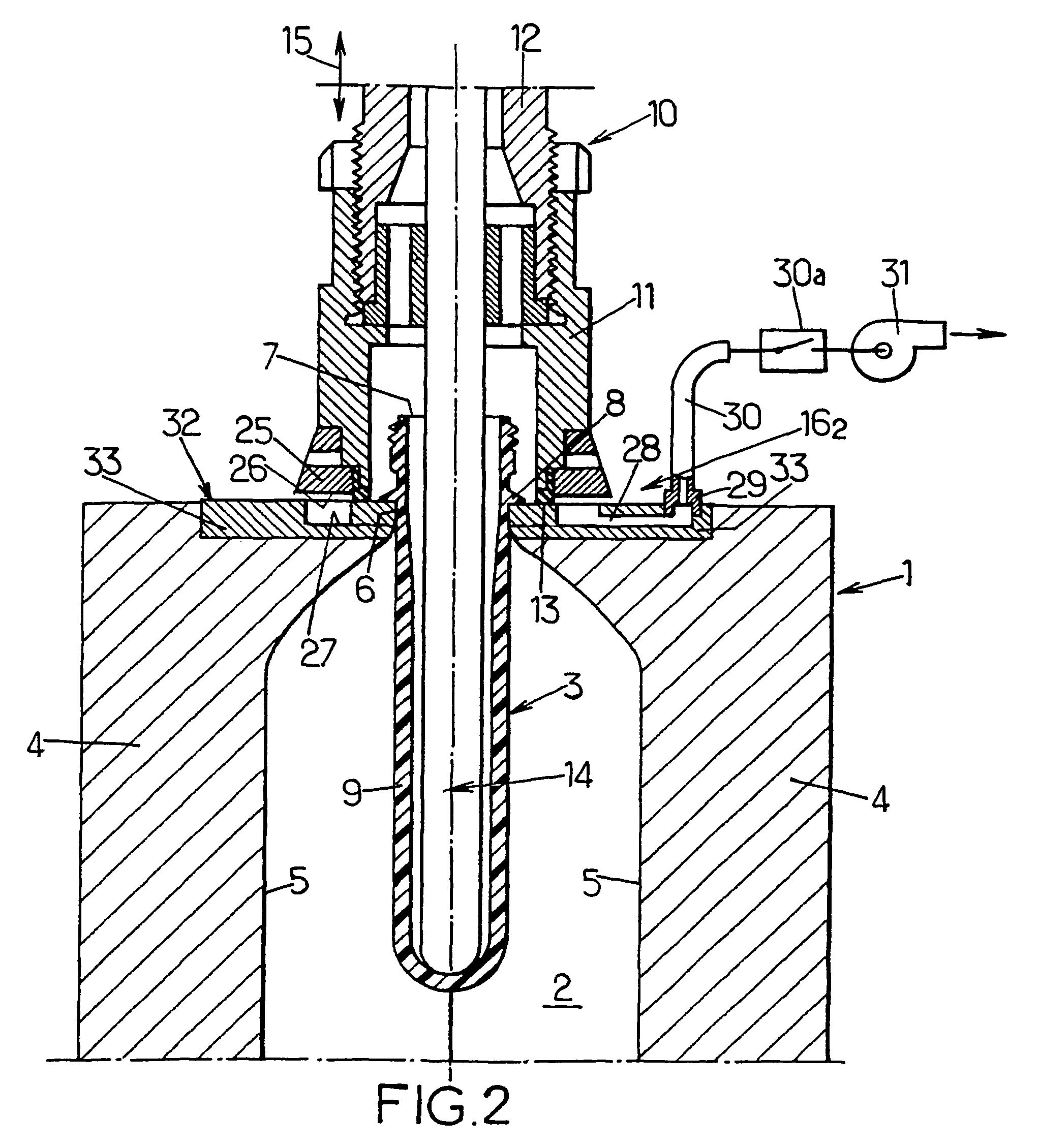
[0020]In the various figures of the accompanying drawings, only the co-operating portions of the mold and of the blow nozzle that are necessary for understanding the invention are shown. In the figures, like elements or portions are designated by like reference numerals.

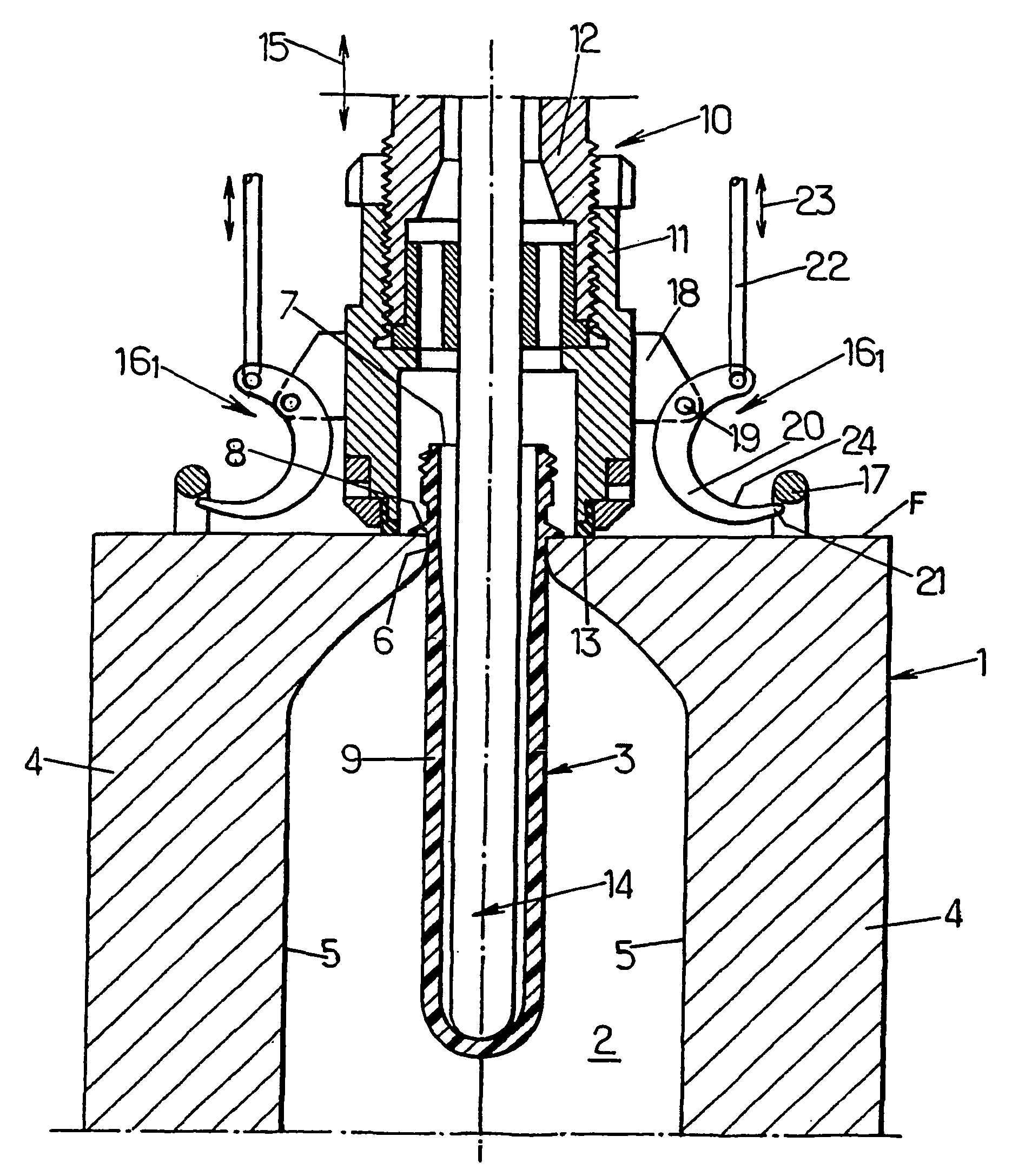
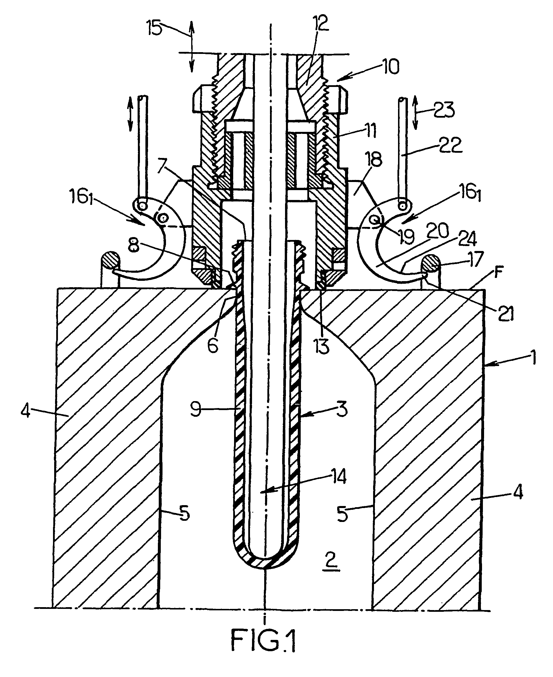
[0021]With reference firstly to FIG. 1, a mold 1 has a mold cavity 2 that has the same shape as a receptacle to be obtained by deforming a rough or blank (e.g. a preform) 3. In particular the mold is of the hinged type or bill-fold type. In which case, the mold 1 comprises two half-molds 4 provided with respective cavity-forming recesses 5 which, when brought together (when the mold is closed) define the mold cavity 2, or most of said cavity when the mold is further provided with a complementary part provided with the cavity-forming recess for the bottom of the receptacle.

[0022]The mold 2 has an external wall F (top wall in FIG. 1) in which the mold cavity 2 opens out via a passageway 6 (neck passageway) via which th...


PUM

PropertyMeasurementUnit
pressureaaaaaaaaaa
pressureaaaaaaaaaa
pressureaaaaaaaaaa

Abstract

A blow-molding installation for manufacturing receptacles from blanks of thermoplastic polymer, said installation comprising a bell-nozzle for blowing a fluid under pressure into a blank (3) disposed in a cavity (2) of a mold (1), the end of the nozzle being in the shape of a bell (11) which is suitable, during blow-molding, for being pressed into leaktight end-to-end abutment against a wall (F) of the mold while capping the neck (7) of the blank that emerges from said wall; said installation further comprises means (161) for securing the nozzle to the wall of the mold by mutual attraction, which means can be activated, after the nozzle has been brought into end-to-end contact with the wall (F) of the mold without flattening a sealing gasket (13), so as to attract the nozzle (10) and the wall (F) towards each other with an attraction force greater than the repulsion force due to the pressure of the blow-molding fluid.

Description

FIELD OF THE INVENTION[0001]The present invention relates to improvements made to blow molding installations, or to stretch-blow molding installations that implement a special nozzle referred to as a “bell-nozzle” and that are for manufacturing receptacles from roughs or blanks of thermoplastic polymer, in particular polyethylene terephthalate (PET), such an installation comprising a blow nozzle of the bell-nozzle type for blowing a fluid under pressure into a blank disposed in a cavity of a mold, said nozzle having its end in the shape of a bell which is suitable, during blow-molding, for being pressed into leaktight end-to-end abutment against a wall of the mold while capping the neck of the blank that emerges from said wall against which said blank is in abutment via an annular collar while its body is engaged in said cavity of the mold.DESCRIPTION OF THE PRIOR ART[0002]A bell-nozzle blow-molding installation is described in document FR-A-2 764 544. In that known arrangement, as ...

Claims


Application Information

Patent Timeline
Patent Type & Authority Patents(United States)
IPC IPC(8): B29C49/58B29C49/56
CPCB29C49/58B29C49/56B29C2049/5806B29C2049/581B29L2031/7158B29C2049/5824B29C2049/5827B29K2067/00B29C2049/5817
Inventor SANTAIS, DIDIERLEGALLAIS, STEPHANE
Owner SIDEL PARTICIPATIONS SAS
Why Eureka
Try Eureka