Magnetic circuit for rotating apparatus

a technology of rotating apparatus and magnetic circuit, which is applied in the direction of magnetic circuit shape/form/construction, electrical apparatus, dynamo-electric machines, etc., can solve the problems of motor cost increase factor and cost increase in a system requiring a nearly complete high dc voltage with energy loss

Inactive Publication Date: 2004-04-06
ENERTEC KOREA
View PDF11 Cites 21 Cited by
  • Summary
  • Abstract
  • Description
  • Claims
  • Application Information

AI Technical Summary

Problems solved by technology

Further, the magnetic circuit in the conventional vertical circuit type electrical motor has another cost increase factor with respect to the maintenance fee and production cost because of a magnetic loss by a magnetic resistance according to multilevel flows of a magnetic field, an energy loss by iron core loss, etc., according to ...

Method used


Image

  • Magnetic circuit for rotating apparatus
  • Magnetic circuit for rotating apparatus
  • Magnetic circuit for rotating apparatus

Examples


Embodiment Construction

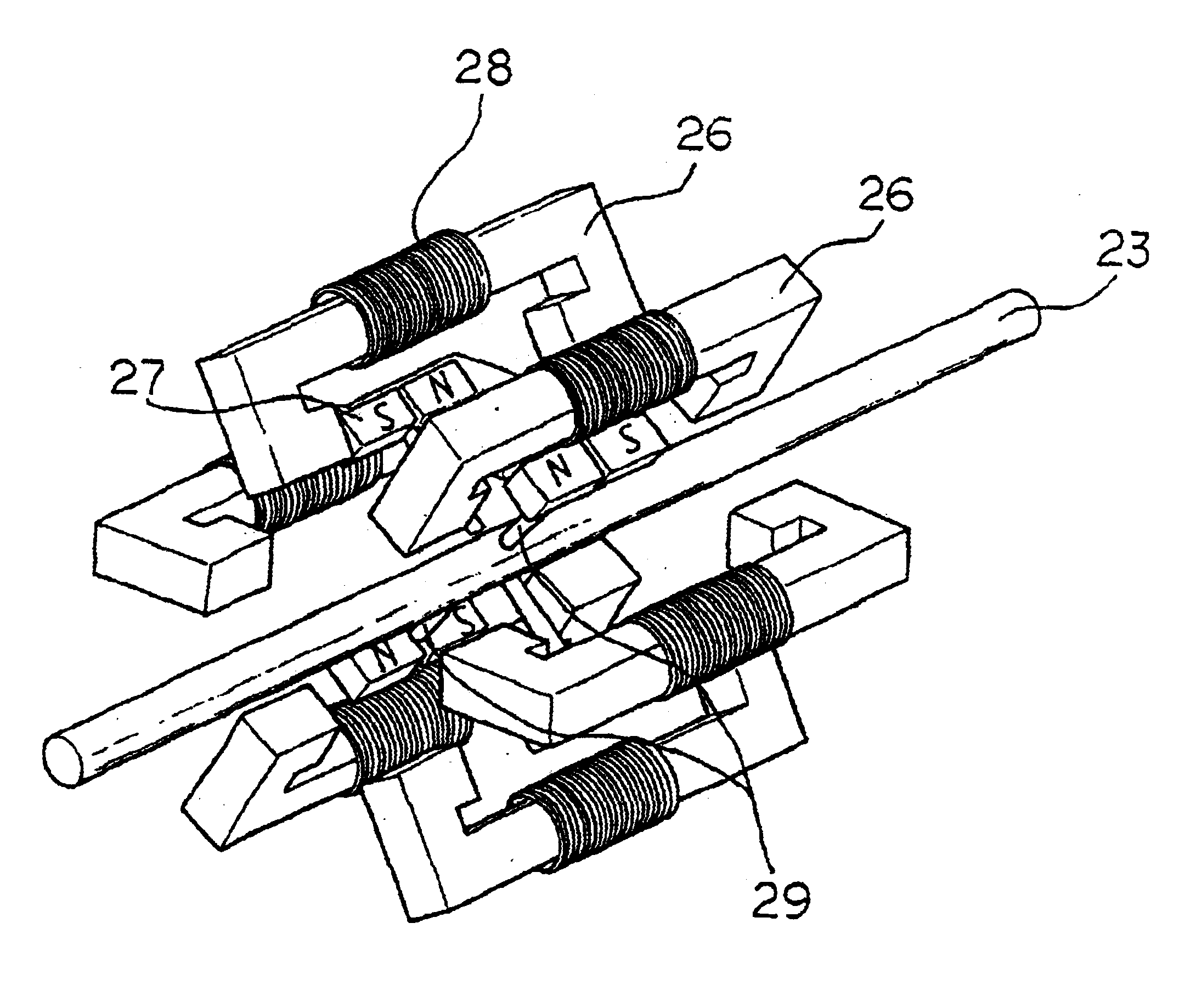
According to one embodiment of the present invention, a magnetic circuit for a rotating apparatus which is employed for a rectangular wave generator or a rectangular wave electric motor includes a rotating shaft, a plurality of supporters fixedly mounted perpendicularly to the rotating shaft, a plurality of rotors each mounted to each end of the plurality of supporters in order for pole pieces(faces) to be parallel with the rotating shaft so that the rotors are rotated by an attraction force and a repulsion force of a magnetic field, and a plurality of stators (armatures) mounted in a certain interval to each other and each having a coil on their body to obtain alternate magnetic field flux from the pole pieces(faces) of the rotors (magnets) occurring upon rotation of the rotors.

Further, according to a preferred characteristic of the present invention, a rectangular wave electric power generator, a annular magnetic field flux deriver, and a mechanical dynamic power generator, a phas...


PUM


Abstract

An energy conversion magnetic circuit is constituted with magnet pole pieces of magnets or armatures which are in parallel with respect to the shaft to obtain a dynamic force or an electromotive force. The magnetic circuit for a generator or an electric motor has a rotating shaft, a plurality of supporters fixedly mounted in a perpendicular direction to the circumference of the rotating shaft, a plurality of rotors arranged in parallel with respect to the shaft on each end of the plurality of supporters to be rotated by attraction force and repulsion force of a magnetic field, and a plurality of armatures having a coil wound on the body thereof. The coil is mounted at an interval outside the rotors and receives induced alternate magnetic flux of the rotors to generate a rectangular wave electromotive force or to obtain a high torque with input of electrical energy. The alternate magnetic flux generated when rotated, and magnet pole piece are arranged in parallel with the rotating shaft

Description

1. Field of the InventionThe present invention relates to a magnetic circuit for energy conversion having a structure that magnets and magnet pole pieces (or planes) of an armature are dispose in parallel with respect to the shaft of an electric motor in order for a flux of a magnetic field to form a magnetic circuit in parallel with the shaft, to thereby obtain a dynamic force or a rectangular wave electromotive force.2. Description of the Prior ArtA rotating apparatus and a power system, which are used so far, is structured vertically (at the right angle) when magnet 5 and magnet pole pieces (or planes) of an armature are traversely disposed (hereinafter, referred to as -with respect to a shaft-), so that a vertical type magnetic circuit is constructed which a flux of a magnetic field is circulated in directions of york 7, armature 6, magnet 5, armature 6, and magnet 5.FIG. 1A is a schematic view of a conventional vertical type electric motor which has a magnetic flux in a vertica...

Claims


Application Information

Patent Timeline
IPC IPC(8): H02K21/12H02K21/24H02K16/00H02K29/00H02K21/18
CPCH02K21/12H02K21/24H02K2201/12
Inventor BAE, YOUN SOO
Owner ENERTEC KOREA
Why Eureka
Try Eureka