Encoder, decoder, and encoding method

A coding device and coding technology, which can be used in code conversion, speech analysis, instruments, etc., and can solve problems such as reducing the bit rate.

Active Publication Date: 2010-12-01
III HLDG 12 LLC
View PDF12 Cites 17 Cited by
  • Summary
  • Abstract
  • Description
  • Claims
  • Application Information

AI Technical Summary

Problems solved by technology

According to this technique, the input signal is divided into a low-frequency part signal and a high-frequency part signal, and the frequency spectrum of the high-frequency part signal is replaced by the frequency spectrum of the low-frequency part signal for encoding, thereby reducing the overall bit rate.

Method used


Image

  • Encoder, decoder, and encoding method
  • Encoder, decoder, and encoding method
  • Encoder, decoder, and encoding method

Examples


Embodiment approach 1

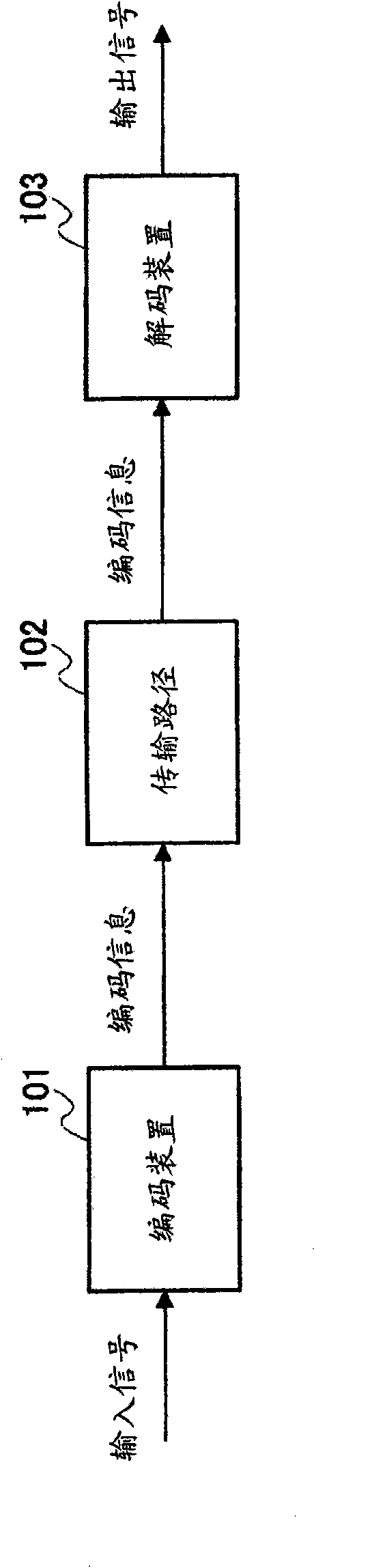
[0033] figure 2 It is a block diagram showing the configuration of a communication system including an encoding device and a decoding device according to Embodiment 1 of the present invention. exist figure 2 In , a communication system includes an encoding device and a decoding device in a state capable of communicating with each other via a transmission path.

[0034] The encoding device 101 divides the input signal every N samples (N is a natural number), and encodes each frame by using the N samples as one frame. Here, it is assumed that an input signal to be coded is expressed as x n (n=0, . . . , N-1). n represents the (n+1)th signal element of the input signal divided every N samples. The encoded input information (encoded information) is sent to the decoding device 103 via the transmission line 102 .

[0035] The decoding device 103 receives the encoded information sent from the encoding device 101 via the transmission path 102, and decodes it to obtain an output...

Embodiment approach 2

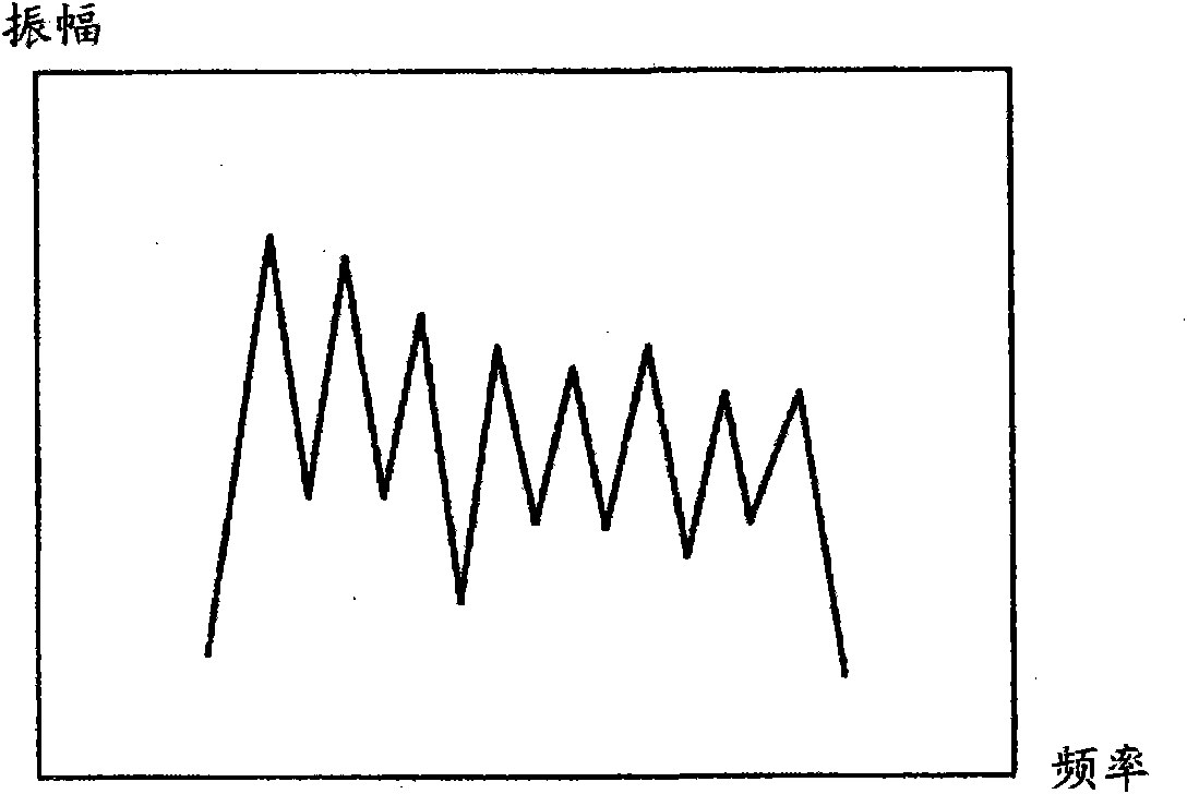
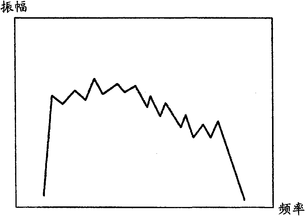
[0147] In Embodiment 1 of the present invention, a case where characteristic information is generated using time-domain signals or coded information has been described as an example. However, in Embodiment 2 of the present invention, using Figure 14 and Figure 15 , the case where the input signal is transformed into the frequency domain and the strength of the harmonic structure is analyzed to generate characteristic information will be described.

[0148] The communication system according to this embodiment is the same as the communication system according to Embodiment 1 of the present invention, except that an encoding device 121 is provided instead of the encoding device 101 .

[0149] Figure 14 It is a block diagram showing the internal main configuration of the encoding device 121 according to Embodiment 2 of the present invention. also, Figure 14 Encoding device 121 shown with image 3 The illustrated encoding device 101 is basically the same, except that a ch...


PUM


Abstract

An encoder capable of reducing the degradation of the quality of the decoded signal in the case of band expansion in which the high band of the spectrum of an input signal is estimated from the low band. In this encoder, a first layer encoding section (202) encodes an input signal and generates first encoded information, a first layer decoding section (203) decodes the first encoded information and generates a first decoded signal, a characteristic judging section (206) analyzes the intensity of the harmonic structure of the input signal and generates harmonic characteristic information representing the analysis result, and a second layer encoding section (207) changes, on the basis of the harmonic characteristic information, the numbers of bits allocated to parameters included in second encoded information created by encoding the difference between the input signal and the first decoded signal before creating the second information .

Description

technical field [0001] The present invention relates to an encoding device, a decoding device, and an encoding method used in a communication system for encoding and transmitting a signal. Background technique [0002] When transmitting voice / music signals through packet communication systems represented by Internet communications, mobile communication systems, etc., compression / encoding techniques are often used in order to increase the transmission power of voice / music signals (music signals). In addition, in recent years, in addition to simply encoding speech / tone signals at a low bit rate, there has been an increasing demand for techniques for encoding speech / tone signals at a wider bandwidth. [0003] To meet such demands, there is a technique of encoding a wide-band signal at a low bit rate (for example, refer to Patent Document 1). According to this technique, an input signal is divided into a low-frequency signal and a high-frequency signal, and the frequency spectr...

Claims


Application Information

Patent Timeline
Patent Type & Authority Applications(China)
IPC IPC(8): G10L19/14G10L21/04H03M7/30G10L19/02G10L19/09G10L19/12G10L19/16G10L21/038
CPCG10L21/038G10L19/0204
Inventor 山梨智史押切正浩
Owner III HLDG 12 LLC
Why Eureka
Try Eureka