Pincer type brake with force-amplifying mechanisms

A technology of caliper brake and booster mechanism, applied in the direction of brake type, axial brake, brake actuator, etc., can solve the problems of high power, difficult maintenance and high cost of the driving device, and achieve low quality, convenient expansion, low cost effect

Inactive Publication Date: 2010-12-08
HENAN POLYTECHNIC UNIV
View PDF7 Cites 25 Cited by
  • Summary
  • Abstract
  • Description
  • Claims
  • Application Information

AI Technical Summary

Problems solved by technology

[0003] The technical problem to be solved by the present invention is the volume, weight, large power of the drive device, high energy consumption, difficult maintenance, and high cost of the brake. It provides a linear motor elevator and a similar braking device with braking requirements.

Method used


Image

  • Pincer type brake with force-amplifying mechanisms
  • Pincer type brake with force-amplifying mechanisms
  • Pincer type brake with force-amplifying mechanisms

Examples


Embodiment 1

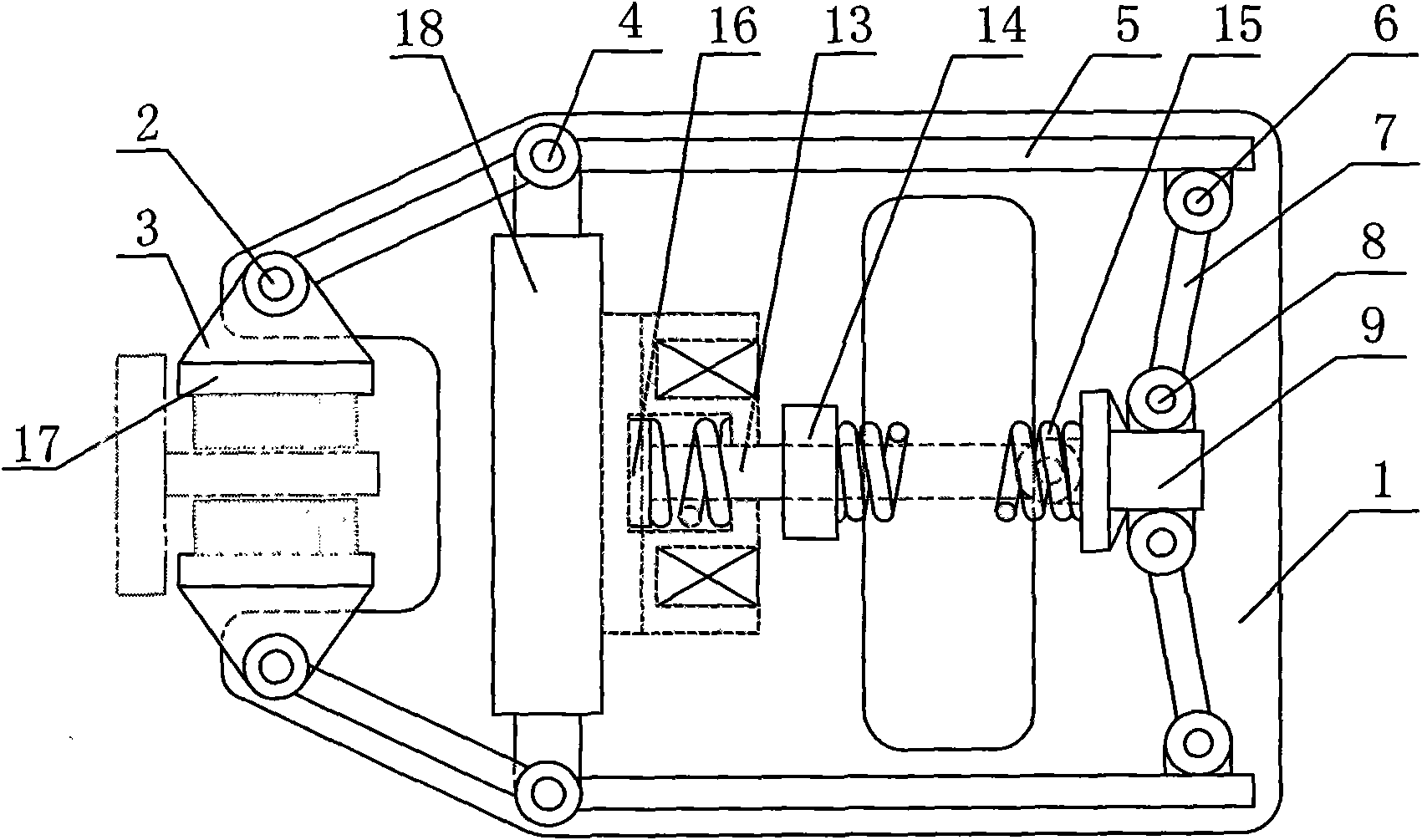
[0023] Such as figure 1 As shown, the caliper brake with booster mechanism includes base 1, brake block hinge shaft 2, brake block 3, swing arm front hinge shaft 4, swing arm 5, swing arm rear hinge shaft 6, and brake booster mechanism The connecting rod 7, the brake connecting rod hinge shaft 8, the sliding block 9, the pushing mechanism 13, the guide block 14, the brake spring 15, the brake spring seat 16, the brake lining 17, and the fixed block 18. The pushing mechanism 13 is an electromagnet, a linear motor, an electric push rod, a hydraulic push rod, an electro-hydraulic push rod, a pneumatic push rod or other pushing mechanisms.

[0024] The fixed block 18 and the guide block 14 are fixed on the base 1. The brake block 3 and the brake lining 17 are hinged on the swing arm through the brake block hinge shaft 2. The brake block 3 can swing around the brake block hinge shaft 2, and the swing arm 5 passes through it. Its own ear plate is hinged with the ear plate on the fixed ...

Embodiment 2

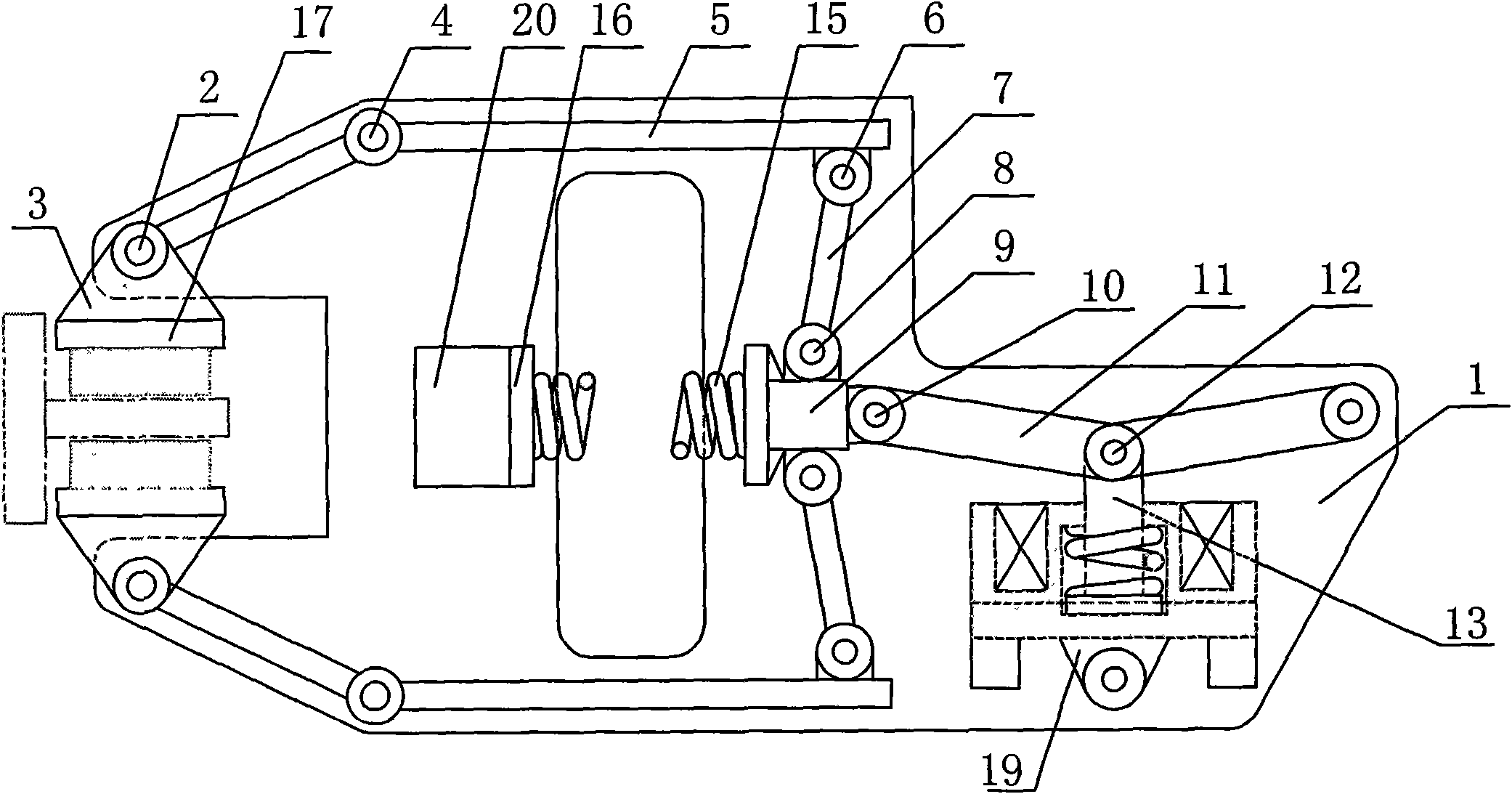
[0032] Such as figure 2 As shown, the caliper brake with dual booster mechanism includes base 1, brake block hinge shaft 2, brake block 3, swing arm front hinge shaft 4, swing arm 5, swing arm rear hinge shaft 6, brake booster Mechanism link 7, brake link hinge shaft 8, slider 9, drive booster mechanism link hinge shaft 10, drive booster mechanism link 11, electromagnet hinge shaft 12, push mechanism 13, brake spring 15, Brake spring seat 16, brake lining 17, fixed block II 19, fixed block III 20.

[0033] The swing arm front hinge shaft 4, the fixed block II 19, and the fixed block III 20 are fixed on the base 1. The swing arm 5 is hinged with the swing arm front hinge shaft 4 through its own ear plate, and the swing arm 5 passes through the upper ear plate. It is hinged with the brake booster linkage 7 and the rear hinge shaft 6 of the swing arm; the brake booster linkage 7 is hinged with the slider 9 through the brake linkage hinge 8; the brake spring 15 is hinged through the...

Embodiment 3

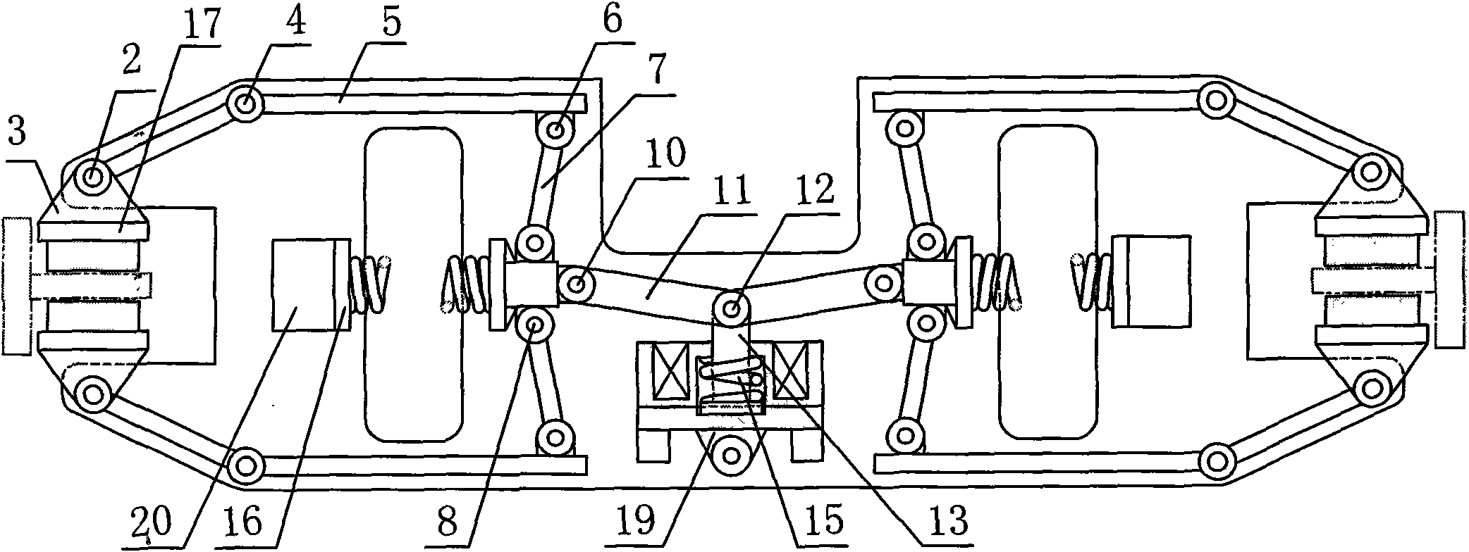
[0041] Such as image 3 Shown, a two-way caliper brake with a double booster mechanism. It is arranged symmetrically on the basis of embodiment 2, and becomes a two-way brake with multiple booster mechanisms working synchronously. Other connections are the same as in Example 2.


PUM


Abstract

The invention discloses a pincer type brake with force-amplifying mechanisms, which can be used in straight-line elevators, hoisters and similar railbrake braking occasions. The pincer type brake comprises a swingable drive rod type force-amplifying mechanism and a brake rod type force-amplifying mechanism, wherein the drive rod type force-amplifying mechanism is connected with an electromagnet, and the brake rod type force-amplifying mechanism is connected with a brake spring; and the force-amplifying mechanisms are articulated with swingable brake arms, the ends of the brake arms are connected with swingable brake blocks used for braking, and the action surfaces of the brake blocks are wear-resistant brake bushes. Because the pincer type brake is provided with one or more force-amplifying mechanisms, the specification size of the brake spring and the powers, the sizes and the weights of the electromagnet and other pushing mechanisms are greatly reduced, the braking force and the driving force are greatly increased, and the pincer type brake is at least 1-2 orders of magnitude higher than the common force-amplification free brake. Because the force-amplifying mechanisms are symmetrically arranged, the two brake arms can be accurately controlled to swing in the same swing angle, thereby the biased action force on brake rails is avoided, the braking reliability is improved, and the braked members are accurately braked in the required positions.

Description

Technical field [0001] The invention can be used in similar rail brake braking situations including linear motor elevators, hoists and the like. Specifically, it involves reducing the size, weight and driving power of the brake, and ensuring that the elevator car and other braked parts are accurately braked in the required position. Background technique [0002] The commonly used caliper brake structure is composed of two swing power arms rotating around a fixed shaft pin, a drive spring, and a driving device. The ends of the two swing power arms are equipped with brake linings for braking on both sides of the guide rail. . The braking force of the brake is proportional to the driving force and the ratio of the lever arm. The greater the driving force, the greater the lever arm ratio, the greater the braking force, and vice versa, the smaller the braking force. Limited by the braking distance and installation space of the brake, the arm ratio can generally only be selected in a...

Claims


Application Information

Patent Timeline
Patent Type & Authority Applications(China)
IPC IPC(8): F16D55/225F16D65/14F16D65/18
Inventor 汪旭东许宝玉封海潮许孝卓
Owner HENAN POLYTECHNIC UNIV
Why Eureka
Try Eureka