Auxiliary pressure relief valve

A technology for pressure relief valves and slide valves, which is applied in the direction of slide valves, valve details, safety valves, etc., and can solve problems such as incomplete pressure relief

Active Publication Date: 2010-12-08
AUTOL TECH
View PDF3 Cites 6 Cited by
  • Summary
  • Abstract
  • Description
  • Claims
  • Application Information

AI Technical Summary

Problems solved by technology

[0003] The purpose of the present invention is to provide an auxiliary pressure relief valve to solve the problem of incomplete pressure relief in the existing volumetric lubrication system

Method used


Image

  • Auxiliary pressure relief valve
  • Auxiliary pressure relief valve
  • Auxiliary pressure relief valve

Examples


Embodiment Construction

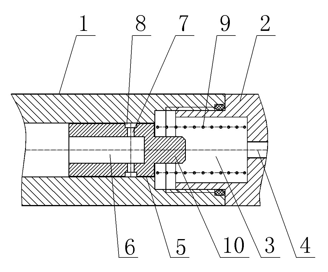
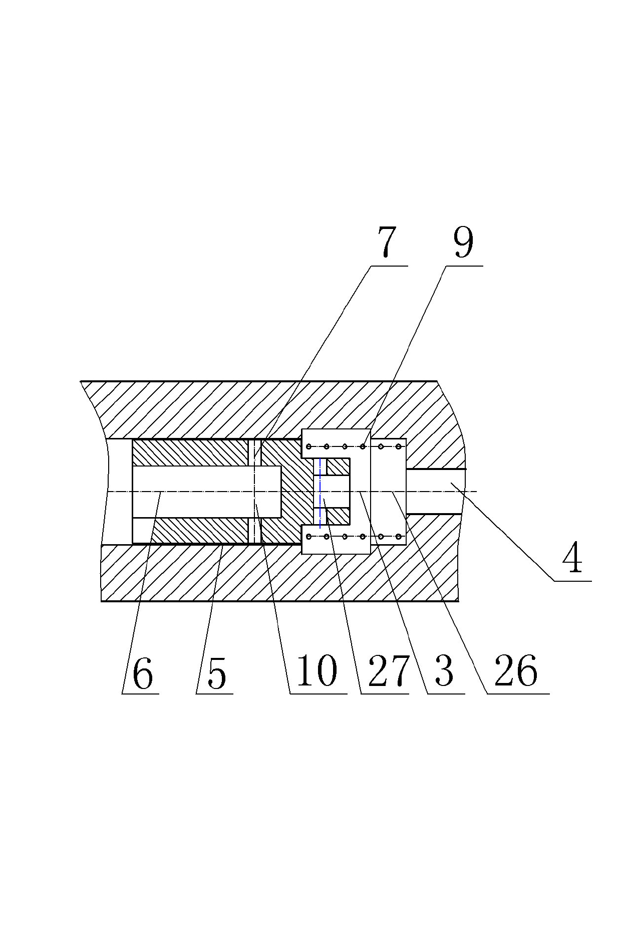
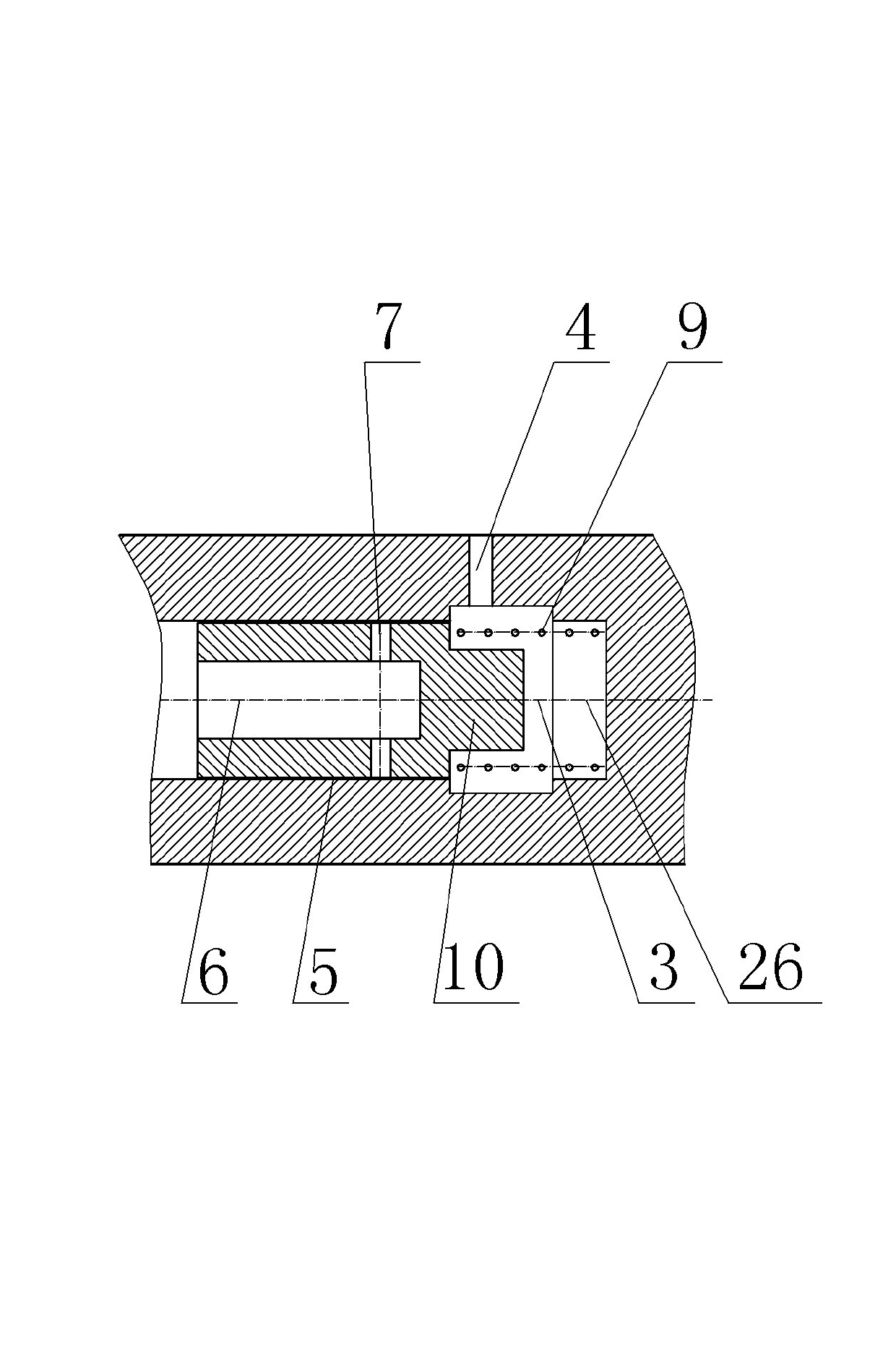
[0023] Embodiment 1 of the auxiliary pressure relief valve of the present invention, such as figure 1 As shown, the slide valve body includes a slide valve body body 1 and a matching body 2. The inner hole of the slide valve body body 1 is a stepped hole, and the matching body 2 is a cylindrical structure with one end open, and the outer wall of the opening end is provided with threads. The large-diameter hole 3 of the stepped hole of the valve body 1 has an internal thread, the slide valve body 1 is threadedly connected with the mating body 2, and a sealing ring is arranged between the two, and the sealing end of the mating body 2 has a seal for connecting with the main oil circuit. The oil outlet hole 4 connected by the pipeline, the slide valve core 5 is slidingly assembled in the small diameter hole of the step hole of the slide valve body body 1, the outer peripheral surface of the slide valve core 5 and the inner wall surface of the small diameter hole of the step hole of...


PUM


Abstract

The invention relates to an auxiliary pressure relief valve which comprises a sliding valve body and a sliding valve element, wherein the sliding valve element is assembled in the sliding valve body in a sliding way; the sliding valve body comprises a sliding valve body main body and a ligand; the ligand and the sliding valve body main body are in seal fit, and the matching position of the ligandand the sliding valve body main body is provided with a pressure relief cavity, the diameter of which is larger than the outer diameter of the sliding valve element; an oil outlet is arranged in the corresponding pressure relief cavity on the circumference of the sliding valve body main body or the ligand; one end of the sliding valve element far away from the ligand is provided with an axial blind hole; an oil outlet which is communicated with the axial blind hole and used for conducting an oil path when the sliding valve element slides under the upstream oil pumping pressure is arranged on the circumference of the sliding valve element; an oil outlet which is communicated with the axial blind hole is arranged on the circumference of the sliding valve element; a pressure relief spring which is used for resetting the sliding valve element after the upstream oil pumping pressure disappears is arranged between the sliding valve element and the ligand; and a seal pressure relief stroke for relieving the pressure of a downstream oil distributor is arranged between the oil outlet and the sliding valve body main body in the resetting process of the sliding valve element.

Description

technical field [0001] The invention relates to the technical field of centralized lubrication, in particular to an auxiliary pressure relief valve. Background technique [0002] Volumetric centralized lubrication technology has been widely used in the field of lubrication technology due to its high reliability, precise oil discharge, low cost and low pressure requirements for lubrication pumps and pipeline systems. In order to ensure the normal operation of the distributor of volume pressure relief centralized lubrication, this technology requires that after the operation of the lubricating pump, the oil pressure near the oil separator group in the main oil circuit must be completely removed, so that the oil separator can supply oil to each lubrication point. Therefore, in this structure, an unloading valve is installed at the oil outlet of the pump in the fuel tank. After the system stops running, the pressure relief port will be opened automatically, and the oil in the ma...

Claims


Application Information

Patent Timeline
Patent Type & Authority Applications(China)
IPC IPC(8): F16N23/00F16K3/00F16K17/04F16K27/04
Inventor 赵大平和兆乐王德全
Owner AUTOL TECH
Why Eureka
Try Eureka