Inductance element, power factor correction circuit and switch power supply

A technology of power factor correction and inductance components, applied in electrical components, inductors with magnetic cores, high-efficiency power electronics conversion, etc., can solve problems such as noise spikes, breakdown switch tubes, etc., to improve reliability and stability , the effect of avoiding the risk of breakdown

Active Publication Date: 2010-12-08
CHINA GREATWALL TECH GRP CO LTD
View PDF0 Cites 4 Cited by
  • Summary
  • Abstract
  • Description
  • Claims
  • Application Information

AI Technical Summary

Problems solved by technology

[0003] The purpose of the embodiments of the present invention is to provide an inductance element, aiming to solve the problem that the power factor correction circuit using the existing inductance element will generate noise spikes and cause breakdown of the switch tube

Method used


Image

  • Inductance element, power factor correction circuit and switch power supply
  • Inductance element, power factor correction circuit and switch power supply
  • Inductance element, power factor correction circuit and switch power supply

Examples


Embodiment Construction

[0020] In order to make the object, technical solution and advantages of the present invention clearer, the present invention will be further described in detail below in conjunction with the accompanying drawings and embodiments. It should be understood that the specific embodiments described here are only used to explain the present invention, not to limit the present invention.

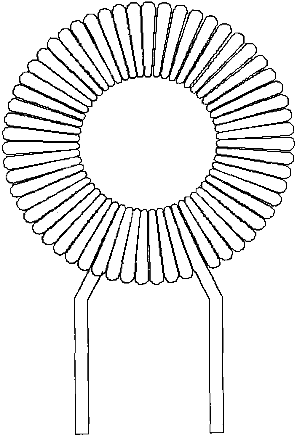
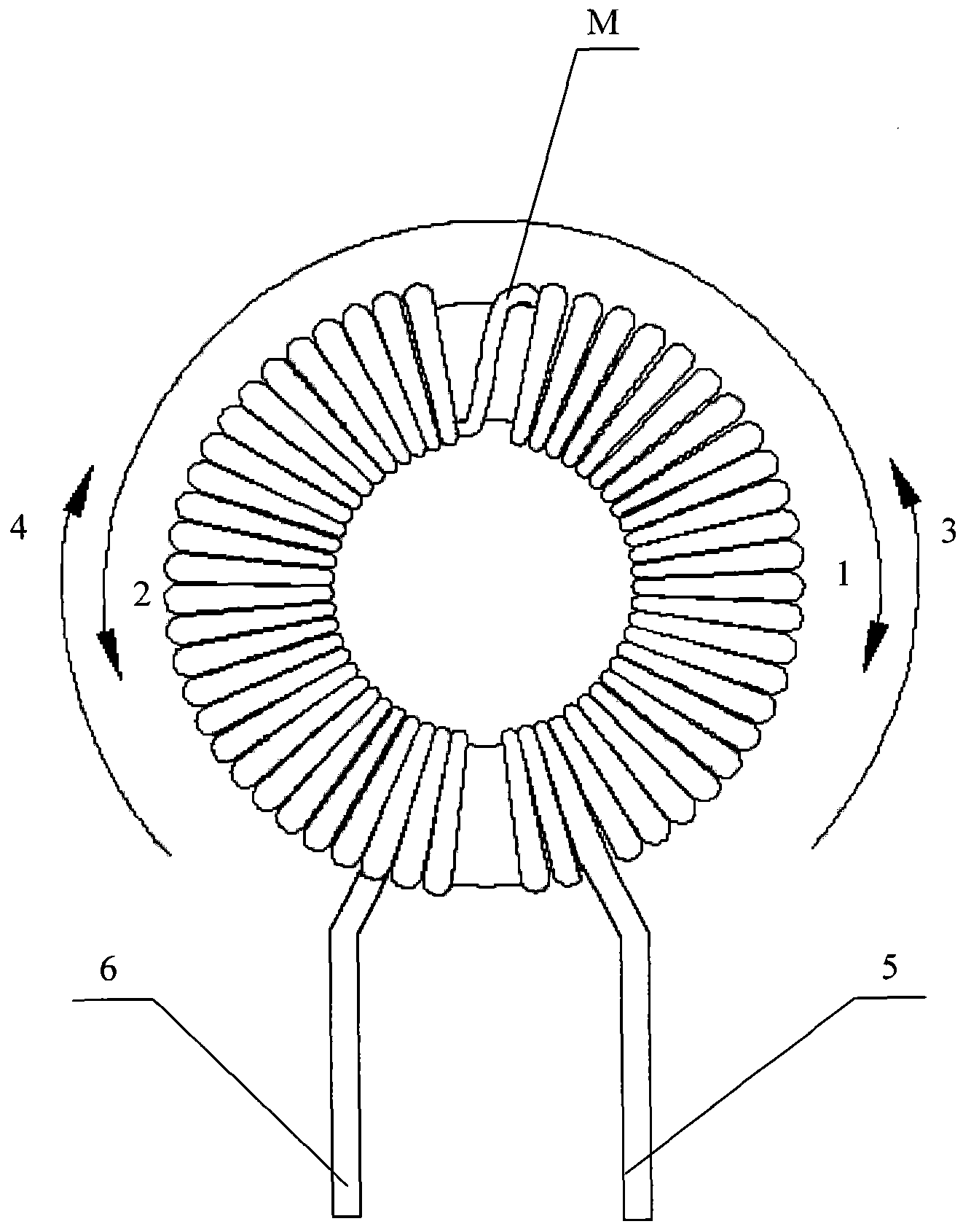
[0021] The inductance element provided by the embodiment of the present invention is to wind the wire from the middle of the annular magnetic core to both sides for a predetermined number of turns, and then lead out the conductive pins respectively, so that the power factor correction circuit using this inductance element will not generate The sharp noise avoids the risk of the switch tube being broken down and improves the reliability and stability of the power factor correction circuit.

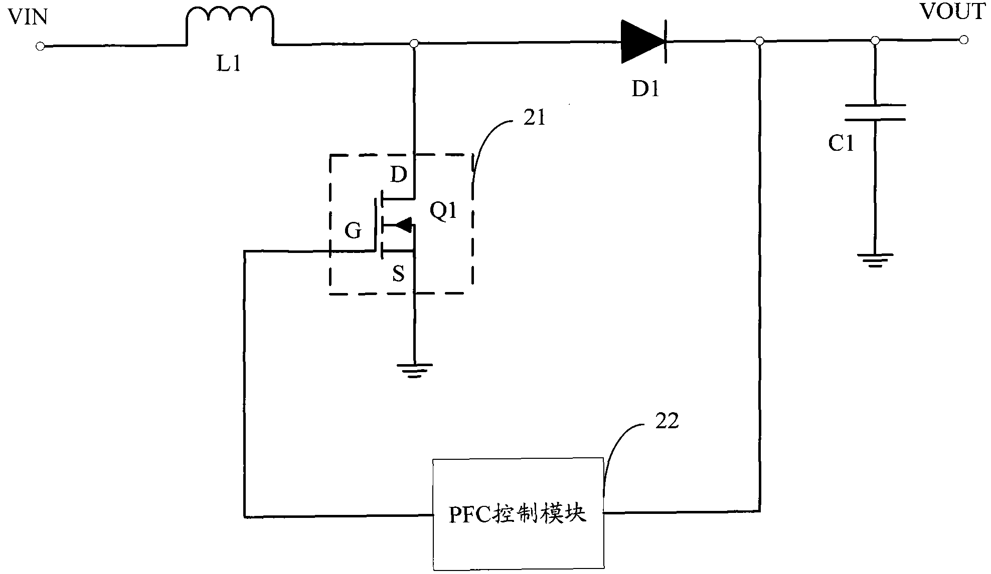
[0022] The inductance element provided by the embodiment of the present invention is mainly used in the power...


PUM


Abstract

The invention is suitable for the field of switch power supplies and provides an inductance element, a power factor correction circuit and a switch power supply. The inductance element comprises a magnetic core and a lead wound on the magnetic core; the magnetic core is an annular magnetic core; the lead is provided with a segmental point and divided into a first lead part and a second lead part by the segmental point; the segmental point of the lead is arranged at any point of the annular magnetic core; the first lead part of the lead is wound for the preset number of turns on one side of the annular magnetic core and then a first conductive pin is drawn out; the second lead part of the lead is wound for the preset number of turns on the other side of the annular magnetic core and then asecond conductive pin is drawn out. In the inductance element provided by the invention, the lead is wound for the preset number of turns on the annular magnetic core from the centre to two sides andthen the conductive pins are respectively drawn out, so that the power factor correction circuit using the inductance element does not generate noise spike, the risk of breaking down the switch tube is avoided, and the reliability and the stability of the power factor correction circuit are improved.

Description

technical field [0001] The invention belongs to the field of switching power supplies, and in particular relates to an inductance element, a power factor correction circuit and a switching power supply. Background technique [0002] The structure of the inductance element formed by the traditional winding method provided by the prior art is as follows: figure 1 As shown, the inductance element first winds the first layer clockwise on the magnetic core, and then winds the second layer counterclockwise, and so on until the required number of turns is completed. The inductance element made by this winding method can stabilize the circuit, but the current waveform output by the switching tube of the power factor correction circuit using this inductance element will produce a large noise spike (such as Figure 4A As shown), the noise spike 100 may break down the switch tube, thereby reducing the reliability and stability of the entire circuit. Contents of the invention [000...

Claims


Application Information

Patent Timeline
Patent Type & Authority Applications(China)
IPC IPC(8): H01F17/06H01F27/30H01F27/28H01F27/29H01F41/06H02M1/42
CPCY02B70/126Y02B70/10
Inventor 李伟平于吉永黄昌宾
Owner CHINA GREATWALL TECH GRP CO LTD
Why Eureka
Try Eureka