
Hair-planting machine

A technology of hair machine and hair nozzle, which is applied in the field of brush machinery, can solve the problems of low hair planting efficiency, time-consuming and manpower, and achieve the effect of saving time and manpower and improving production efficiency

Inactive Publication Date: 2010-12-15
YANGZHOU HAIXING CNC BRUSH MACHINERY
View PDF8 Cites 20 Cited by
  • Summary
  • Abstract
  • Description
  • Claims
  • Application Information

AI Technical Summary

Problems solved by technology

This tufting machine can only perform tufting action. The brush bottom plate needs to drill the brush holes on the drilling machine first, then remove it from the drilling machine, and then install it on the workbench of the tufting machine for tufting. It is necessary to ensure that the position of the brush hole is accurate on the workbench. Due to the repeated disassembly, installation and calibration of the brush base plate, it takes a lot of time and manpower, which makes the hair planting efficiency low.

Method used


Image

  • Hair-planting machine
  • Hair-planting machine
  • Hair-planting machine

Examples


Embodiment Construction

[0017] The following examples illustrate the present invention, but the present invention is not limited to the following examples.

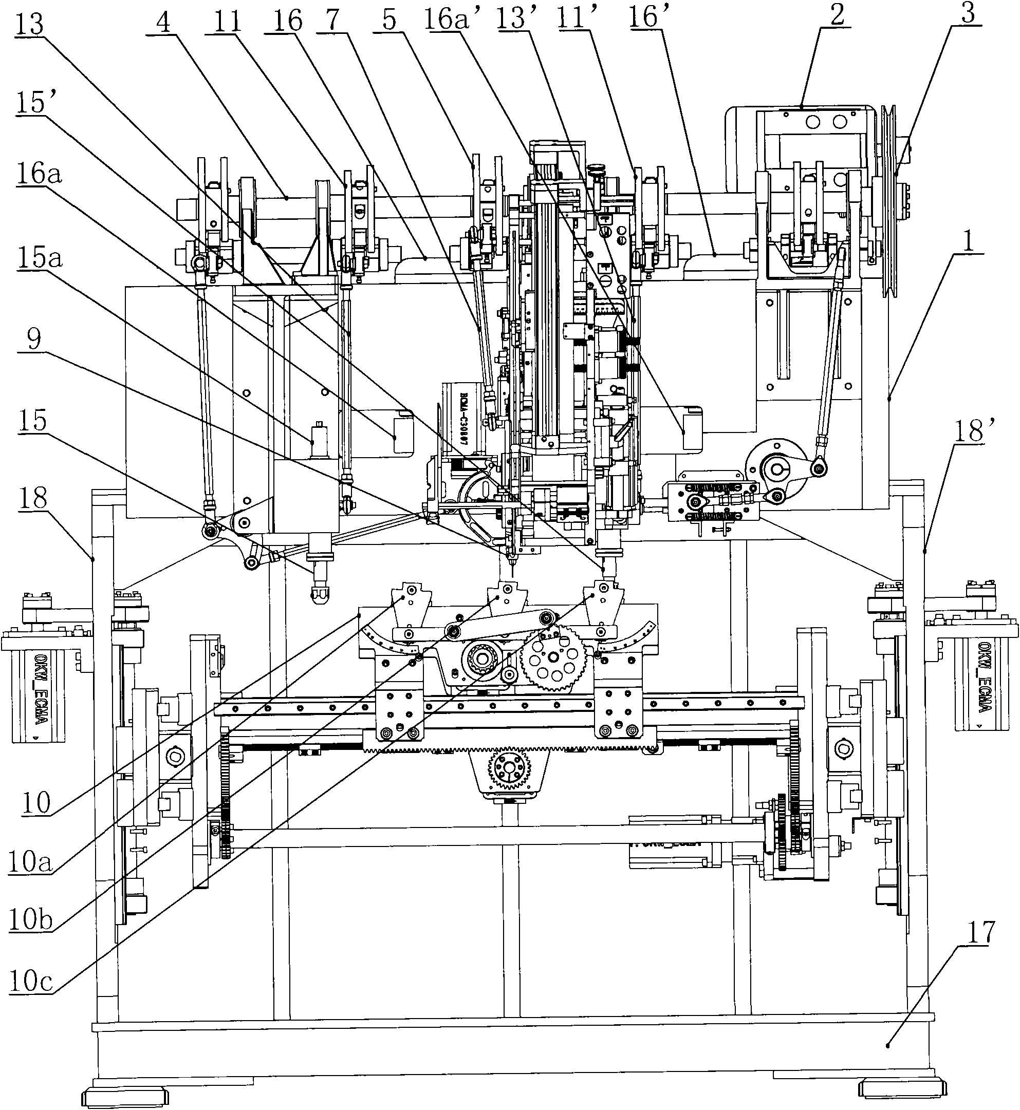
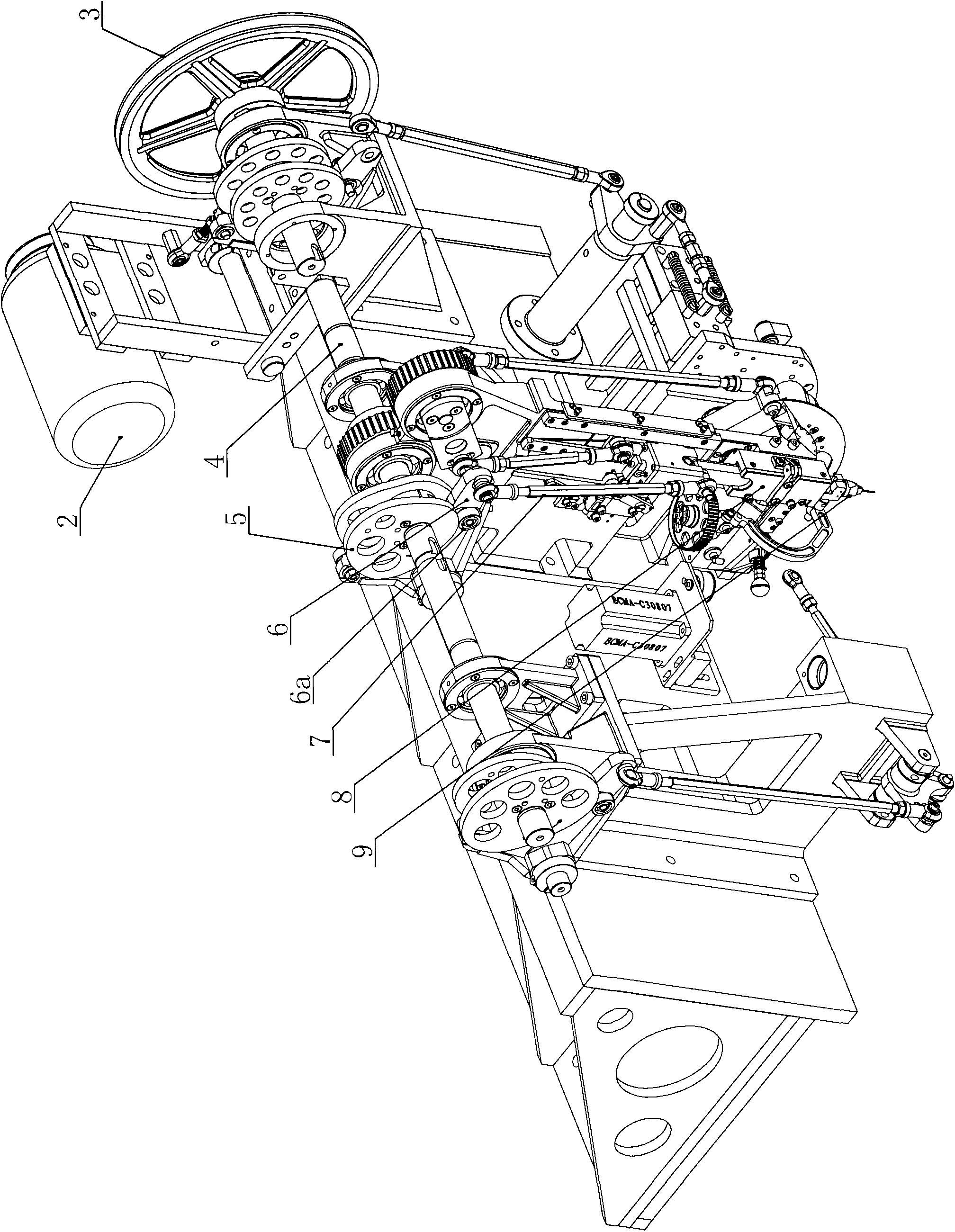
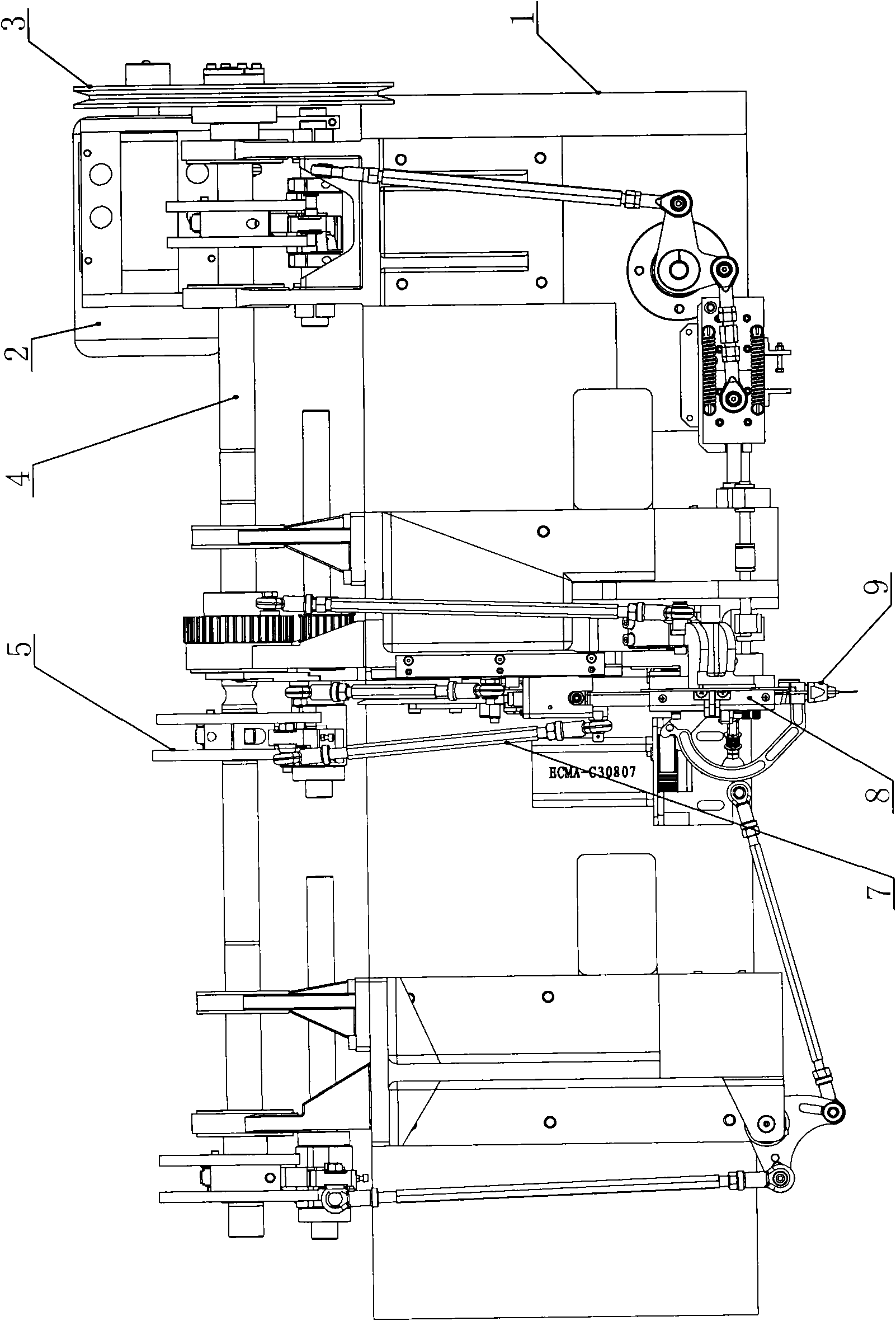
[0018] Such as figure 1 As shown, the tufting machine of the present invention includes a frame 1 on which a main motor 2, a main shaft 4, a brush workbench 10 and a nozzle movement mechanism are installed, and the main motor 2 is connected to the main shaft 4 through a main shaft pulley 3.

[0019] The brushing machine workbench comprises a base 17 and wall panels connected to the both sides of the base 17. The inner sides of the left wall panel 18 and the right wall panel 18' are respectively provided with a lift movement support, a front and rear movement support and a swing support. The lift movement supports on both sides are respectively It can move up and down along the vertical guide rails on the left and right wall panels. The front and rear movement brackets are respectively located inside the lifting movement brackets and can move for...


PUM


Abstract

The invention discloses a hair-planting machine in the field of hairbrush machinery. A stander is provided with a main motor, a main shaft, a brush body workbench, a hair mouth movement mechanism and drilling mechanisms, wherein the main motor drives the main shaft to rotate; a hair mouth conjugate cam and drilling conjugate cams are all arranged on the main shaft; the upper ends of drilling conjugate rockers are meshed with the corresponding drilling conjugate cams, while lower ends are hinged with the upper ends of corresponding drilling connecting rods; the lower ends of the drilling connecting rods are hinged with the middle parts of corresponding drill stems; the drill stems are positioned in drill stem holes of corresponding drill stem seats and can slide up and down along the corresponding drill stem holes; the upper ends of each drill stem are provided with a drill stem driving wheel and are driven through belts by corresponding drill stem drive motors, while the lower ends are provided with a drill bit and are parallel to a hair mouth; two sets of drilling mechanisms are positioned on the two sides of the hair mouth respectively; a space between a first drill bit and the hair mouth is twice that between a second drill bit and the hair mouth; and drilling and hair planting are sequentially finished after a bottom plate of a brush body is fixed on the workbench without replacing a fixture and recalibrating positions. Therefore, time and labor are greatly saved and the production efficiency is improved.

Description

technical field [0001] The invention relates to a brush machine, in particular to a hair planting machine. Background technique [0002] At present, tufting machines are widely used in tufting on brush heads such as daily-use brushes and industrial brushes. It mainly cuts and shapes common round iron wires or flat iron wires and implants them into the brush body together with wool. [0003] The Chinese utility model patent with the application number of 201020108658.1 discloses a wool planting machine workbench, which includes a base and wall panels connected to both sides of the base. The lifting motion brackets can move up and down along the vertical guide rails on the left and right wall panels respectively. The front and rear motion brackets are located inside the lifting motion brackets and can move forward and backward along the horizontal guide rails inside the lifting motion brackets. They are respectively hinged on the front and rear moving brackets, and the swingi...

Claims


Application Information

Patent Timeline
IPC IPC(8): A46D3/06
Inventor 王勇
Owner YANGZHOU HAIXING CNC BRUSH MACHINERY
Learn More