Method for assembling rubber dam in slope-shaped river channel
A rubber dam, slope type technology, applied in the field of rubber dam installation, can solve the problems of uneven force on the dam bag, unsightly dam shape, affecting visual effects, etc., and achieves reduced stress concentration, high compressive strength, and consumption saving. Effect
- Summary
- Abstract
- Description
- Claims
- Application Information
AI Technical Summary
Problems solved by technology
Method used
Image

Examples
Embodiment 1
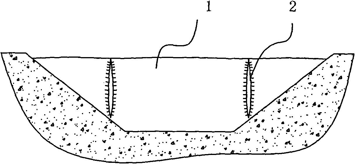
[0024] It is used in the construction of water storage and power generation. The width of the river is 90 meters; the width between the slope lines 5 is 70 meters, and the design interception water level is 5 meters. Such as Figure 1-4 shown.
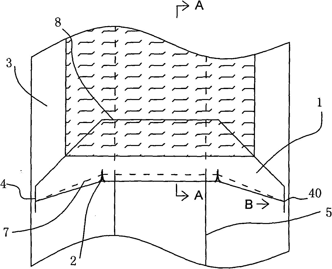
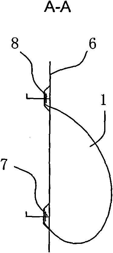
[0025] 1), set up the upper and lower anchor grooves and the top anchor groove 4; at the bottom of the river 3 (river bottom 6), set up the upper and lower anchor grooves cross-cutting the river 3 at an interval of 11m; wherein the upstream anchor groove 8 exceeds the slope line of the river After 0.5m from the slope line 5, it turns to the downstream direction, and the turning angle is 40° (keep the depth of the groove unchanged on the slope); the downstream anchor groove 7 turns to the downstream direction after exceeding 0.5m from the river slope line 5, and the turning angle is less than The turning angle of the upstream anchoring groove 7 (keep the depth of the groove unchanged on the slope) ensures that the two grooves leave a ...
Embodiment 2
[0032] Applied to large-scale agricultural irrigation water storage occasions. The width of the river is 12 meters; the width between the slope lines 5 is 9 meters, and the design interception water level is 1.5 meters. Such as Figure 1-4 shown.
[0033] 1), set up the upper and lower anchor grooves and the top anchor groove 4; at the bottom of the river 3 (river bottom 6), set up the upper and lower anchor grooves that cross the river 3 at an interval of 2.1m; wherein the upstream anchor groove 8 exceeds the slope of the river After 0.4m of the line 5, it turns downstream, and the turning angle is 50° (keep the depth of the groove unchanged on the slope); the downstream anchor groove 7 turns downstream after 0.4m beyond the river slope line 5, and the turning angle It is smaller than the turning angle of the upstream anchor groove 7 (keep the depth of the groove unchanged on the slope), and ensure that the two grooves leave a horizontal top anchor with a length of 1m on th...
Embodiment 3
[0040] Applied to urban beautification and water storage occasions. The width of the river is 120 meters; the width between the slope lines 5 is 100 meters, and the design interception water level is 4.0 meters. Such as Figure 1-4 shown.
[0041] 1), set up the upper and lower anchor grooves and the top anchor groove 4; at the bottom of the river 3 (river bottom 6), set up the upper and lower anchor grooves that cross the river 3 at an interval of 7.5m; where the upstream anchor groove 8 exceeds the river slope After 0.4m of the line 5, it turns downstream, and the turning angle is 45° (keep the depth of the groove unchanged on the slope); the downstream anchor groove 7 turns downstream after 0.4m beyond the river slope line 5, and the turning angle It is smaller than the turning angle of the upstream anchor groove 7 (keep the depth of the groove unchanged on the slope), and ensure that the two grooves leave a horizontal top with a length of 1.5m on the upper edge of the ri...
PUM
| Property | Measurement | Unit |
|---|---|---|
| Turning angle | aaaaa | aaaaa |
Abstract
Description
Claims
Application Information
 - R&D
- Intellectual Property
- Life Sciences
- Materials
- Tech Scout
- Unparalleled Data Quality
- Higher Quality Content
- 60% Fewer Hallucinations
Browse by: Latest US Patents, China's latest patents, Technical Efficacy Thesaurus, Application Domain, Technology Topic, Popular Technical Reports.
© 2025 PatSnap. All rights reserved.Legal|Privacy policy|Modern Slavery Act Transparency Statement|Sitemap|About US| Contact US: help@patsnap.com