Anti-contraction optical cable and production method thereof

A manufacturing method and anti-shrinkage technology, applied in the direction of fiber mechanical structure, etc., can solve the problems of difficult stripping, high price, and low yield of optical cables, and achieve the effects of wide temperature range, simple manufacturing process, and high qualified rate of finished products

Inactive Publication Date: 2010-12-15
蒋菊生
View PDF9 Cites 13 Cited by
  • Summary
  • Abstract
  • Description
  • Claims
  • Application Information

AI Technical Summary

Problems solved by technology

Commonly used optical cables in the field of communication include central bundle tube type, layer twisted type and skeleton type; central tube type optical cable is a structural form in existing optical cables, which includes a loose tube located in the center of the cable, and the loose tube contains multiple The loose tube is also coated with a protective layer to prevent water and moisture from entering the cable and then penetrates along the longitudinal direction of the cable, and the sheath layer is placed outside the protective layer; when the external temperature of this type of optical cable changes, the loose tube will A certain degree of shrinkage will occur, which will cause the optical fiber in the tube to be stressed, and when the optical system is laid in an area with a large temperature difference, this situation will be further aggravated, and even cause communication interruption accidents
So far, the industry has studied the optical cable that prevents the retraction of the loose tube; the application date is 2005.8.25, the application number is 200520106358.9, the authorized announcement number is CN 2824073Y, and the name is: a retractable, fully water-blocking, easy-to-open str

Method used


Image

  • Anti-contraction optical cable and production method thereof
  • Anti-contraction optical cable and production method thereof
  • Anti-contraction optical cable and production method thereof

Examples


Embodiment 1

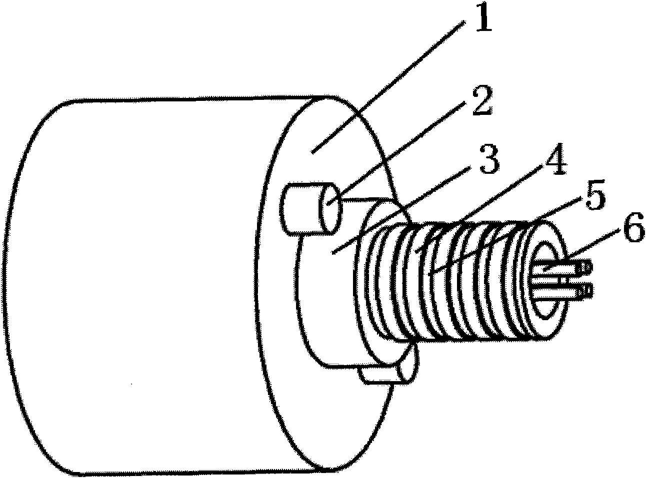
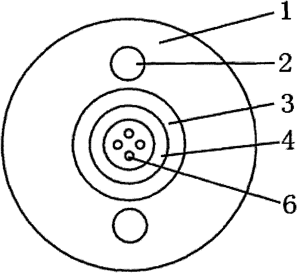
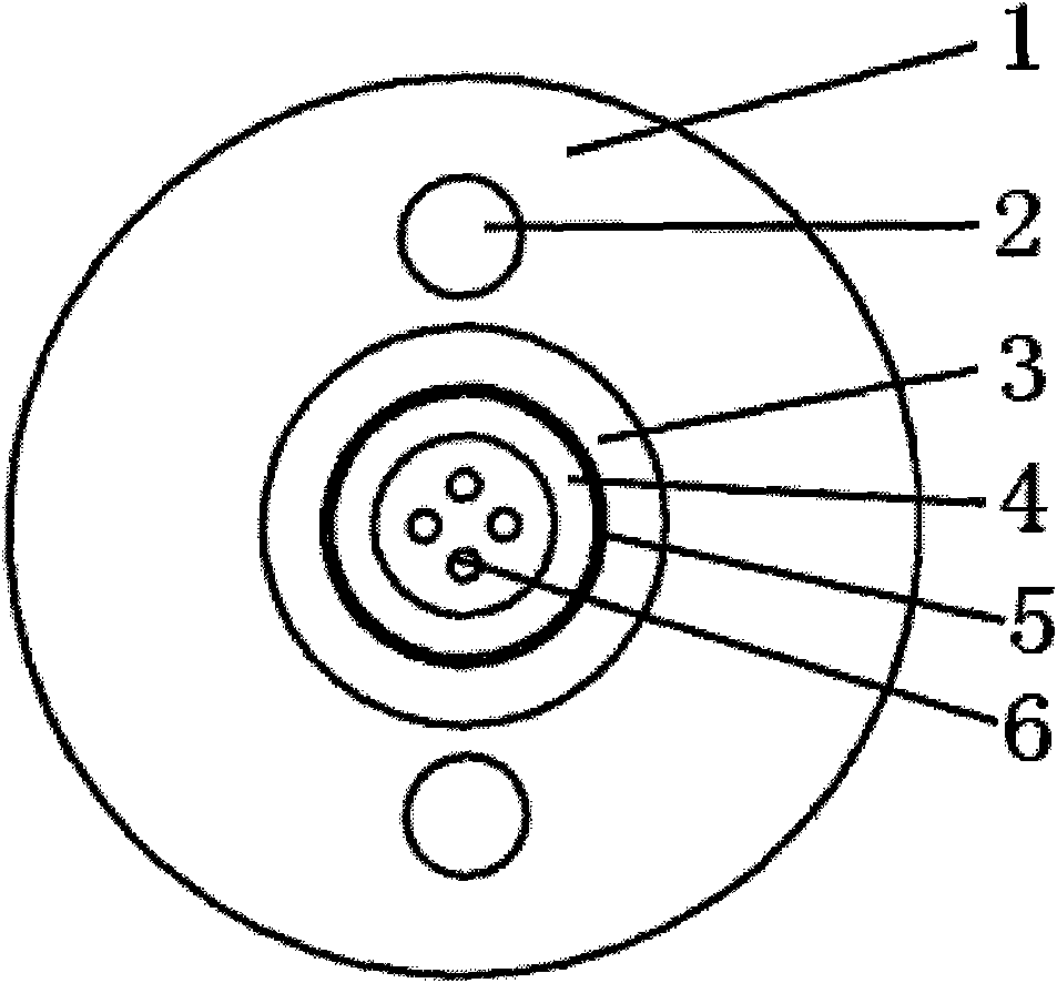
[0042] see Figure 1-Figure 3 , shrink-proof optical cable, which includes: a loose tube located in the center of the cable; a protective layer 3 covering the loose tube; a sheath layer 1 coated outside the protective layer; located between the sheath layer and the protective layer and a plurality of optical fibers 6 inside the loose tube; it is characterized in that: the outer surface of the loose tube is successively distributed with tube bodies 4 and grooves 5; the inner surface of the protective layer has corresponding The protrusion; the gap between the loose tube and the protective layer is filled with water blocking material. The groove is annularly penetrating through the outer surface of the loose tube, and does not go through the tube wall of the loose tube.

Embodiment 2

[0044] see Figure 4-Figure 6, which is basically the same as the first embodiment, except that the groove is partially cut on the outer surface of the loose tube, and does not penetrate through the wall of the loose tube.

Embodiment 3

[0046] see Figure 7 , and refer to Figure 5 and Image 6 , which is basically the same as the second embodiment, except that the width of the groove is narrower and the depth is shallower.


PUM

PropertyMeasurementUnit
Widthaaaaaaaaaa
Thicknessaaaaaaaaaa

Abstract

The invention relates to the technical field of optical transmission communication carrier, in particular to an anti-contraction optical cable. The anti-contraction optical cable comprises a loose tube arranged at the center of the optical cable, a protection layer (3) covering the loose tube, a sheath layer (1) covering the protection layer, an reinforcer (2) arranged between the sheath layer and the protection layer and a plurality of optical fibers (6) arranged in the loose tube. The anti-contraction optical cable is characterized in that tube bodies (4) and grooves (5) are alternately distributed on the outer surface of the loose tube in sequence, the inner surface of the protection layer is provided with corresponding bulges, and the gap between the loose tube and the protection layer is stuffed with water blocking matters. The invention also discloses a production method of the anti-contraction optical cable. The invention has the advantages that the cable has less contraction, easier stripping, wide temperature adaptation scope, simple production process and high finished product yield.

Description

technical field [0001] The invention relates to the technical field of optical transmission and communication carriers, in particular to an optical cable capable of preventing shrinkage and a manufacturing method thereof. Background technique [0002] Due to the large amount of information transmitted, optical cables are increasingly widely used in the field of communication transmission. Commonly used optical cables in the field of communication include central bundle tube type, layer twisted type and skeleton type; central tube type optical cable is a structural form in existing optical cables, which includes a loose tube located in the center of the cable, and the loose tube contains multiple The loose tube is also coated with a protective layer to prevent water and moisture from entering the cable and then penetrates along the longitudinal direction of the cable, and the sheath layer is placed outside the protective layer; when the external temperature of this type of op...

Claims


Application Information

Patent Timeline
IPC IPC(8): G02B6/44
Inventor 蒋菊生
Owner 蒋菊生
Why Eureka
Try Eureka