
Case and cabinet dehumidifying circular dryer

A technology of circulating drying and chassis, applied in the direction of instruments, humidity control, control/regulation systems, etc., can solve the problem of dehumidification of boxes and cabinets that cannot be fundamentally solved, affect the safe operation of power control equipment, and cannot separate moisture from air and water. and other problems, to achieve the effect of simple structure, convenient installation and maintenance, and no vibration

Inactive Publication Date: 2011-12-28
溧阳市科燕新技术开发所 +3
View PDF0 Cites 0 Cited by
  • Summary
  • Abstract
  • Description
  • Claims
  • Application Information

AI Technical Summary

Problems solved by technology

[0003] After the existing high-voltage electric cabinets, indoor and outdoor control boxes and power boxes are put into operation, the moisture-proof treatment remains at the stage where the humidity controller is matched with the heater. Heating, so that the hot and humid air after heating rises naturally. After the hot and humid air rises, it meets the electrical components in the box. Instead, the hot and humid air will easily condense on the electrical components. In fact, it cannot fundamentally solve the problem of dehumidification in the box and cabinet. , because the moisture in the humid air in the box and cabinet is not discharged out of the box and cabinet, which reduces the insulation level and increases the probability of accidents
[0004] At present, the humidity controller is used to start the heater to work in the box and cabinet, but the humid air in the box and cabinet cannot be separated from gas and water. The electrical equipment is still damp, the insulation is reduced, and even the electrical equipment is damp and broken down, which seriously affects the safe operation of the power control equipment.

Method used

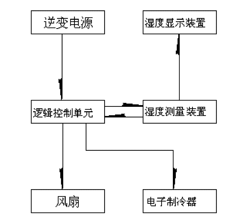
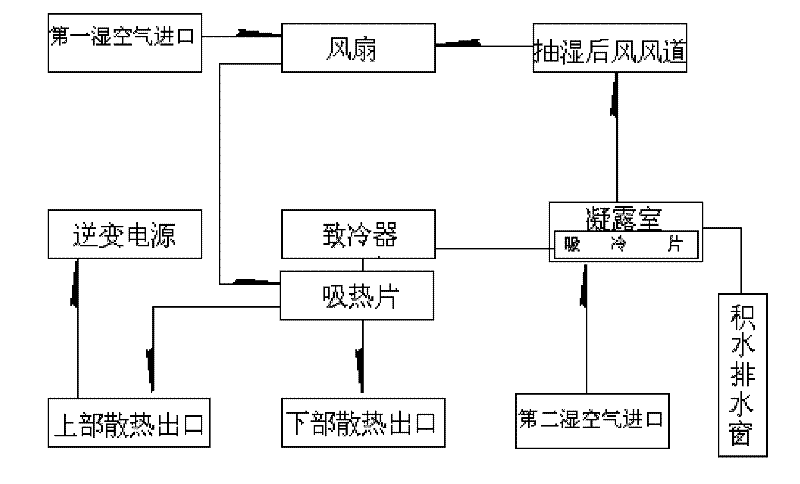
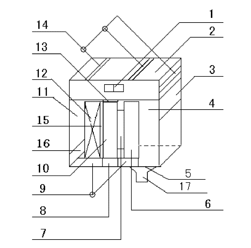

Image

  • Case and cabinet dehumidifying circular dryer
  • Case and cabinet dehumidifying circular dryer
  • Case and cabinet dehumidifying circular dryer

Examples


Embodiment Construction

[0019] In order to make the technical means, creative features, objectives and effects of the present invention easy to understand, the present invention will be further explained below in conjunction with specific embodiments.

[0020] The present invention includes a hexahedral casing and an inverter power supply chassis 2, a fan 12, an electronic refrigerator 7 and a condensation chamber 4 installed in the casing. The inverter power supply chassis 2 is installed above the casing and also includes The control board 16 below the left side of the casing controls the air inlet volume of the second humid air inlet 3. The height of the control board 16 is higher than the bottom of the fan 12, so that the air inlet volume of the second humid air inlet 3 can be controlled by adjusting the control board 16 , A first humid air inlet 11 is provided above the control board 16, and the inverter power supply converts the higher AC and DC voltages into a low-voltage power supply suitable for ...


PUM


Abstract

The invention relates to a case and cabinet dehumidifying circular dryer which comprises a shell, a fan and an electronic refrigerator, wherein the fan and the electronic refrigerator are installed in the shell, an inverse power supply case (2) is arranged above the shell, and the shell is also provided with a condensation chamber (4), a hot end of the electronic refrigerator (7) is connected with a heat absorption piece (10), a cold absorption piece (6) connected with a cold end of the electronic refrigerator (7) is arranged in the condensation chamber (4), a sealed shell (15) adapted to the heat absorption piece (10) is installed on the heat absorption piece (10), the fan (12) is mounted on one surface of the sealed shell (15), an air opening of the fan faces the heat absorption piece (10), a first humid air inlet (11) is also arranged on the shell, and a control board (16) for controlling the air input of a second humid air inlet (3) is arranged below the first humid air inlet (11). The invention can radically solve the moisture prevention and dehumidification problems in a case and a cabinet and has the advantages of no noise, no vibration, no pollution, simple and miniaturized structure, lower cost, durability, reliability, convenient installation and maintenance and the like.

Description

Technical field [0001] The invention relates to a dryer, in particular to a box and cabinet dehumidification circulating dryer. Background technique [0002] At present, our country's electric high-voltage cabinets, indoor and outdoor switch and knife control boxes and power boxes are equipped with various electrical and electronic components in the box. These accessories are responsible for various control and execution functions. These accessories require Usually moisture-proof and moisture-proof, working in a dry environment. [0003] These existing high-voltage power cabinets, indoor and outdoor control boxes and power boxes are put into operation and are treated with moisture-proof treatment. They all stay at the stage of matching the humidity controller and the heater. After the heater is put into operation, only the humid air is removed. Heating makes the heated hot and humid air rise naturally. After the hot and humid air rises, it will meet the electrical components in th...

Claims


Application Information

Patent Timeline
Patent Type & Authority Patents(China)
IPC IPC(8): G05D22/02H02B1/56
Inventor 姬金富戴峰刘春江周斌全周彪姬俊鹏史冀
Owner 溧阳市科燕新技术开发所
Learn More