
Electromagnetic shielding conformal optical window with longitude and latitude-shaped mesh structure

A technology of electromagnetic shielding and optical windows, applied in the direction of magnetic field/electric field shielding, electrical components, etc., can solve the problems of electromagnetic interference of optical windows, difficulty in uniform distribution of metal grids, etc., and achieve high-performance anti-electromagnetic interference performance, High-efficiency anti-electromagnetic interference performance and the effect of overcoming uneven distribution of periods

Inactive Publication Date: 2011-11-16
HARBIN INST OF TECH
View PDF9 Cites 0 Cited by
  • Summary
  • Abstract
  • Description
  • Claims
  • Application Information

AI Technical Summary

Problems solved by technology

[0003] With the increasingly complex electromagnetic environment in space, there are serious electromagnetic interference problems in optical windows in the fields of telemetry and remote sensing, medical diagnosis, secure communication, aerospace and other fields: not only space interference signals from nuclear radiation, lightning pulses, cosmic rays, etc., There are also civilian signals such as television broadcasting and satellite communications, and military interference signals such as microwave weapons and electromagnetic bombs; The signal extraction, detection and processing circuits generate strong electromagnetic interference, which may even lead to energy saturation, blinding, or even destruction of the photoelectric detector, which seriously affects the normal operation of the photoelectric detection system
[0009] 1. US Patent US4871220 "Short wavelength pass filter having a metal mesh on a semiconductor substrate" describes a metal grid with a square structure, which is used to achieve the anti-electromagnetic interference performance of the optical window; however, the metal grid with a square structure is difficult Achieve uniform distribution over conformal optical windows
[0010] 2. Patent 03135313.5 "an observation window for electromagnetic shielding" uses a single or multiple wire mesh and a semiconductor quantum well structure to form an electromagnetic shielding structure, which can achieve a shielding efficiency of more than 50dB within 10GHz. The light transmittance reaches more than 50%; however, it is also difficult for this metal grid to achieve uniform distribution on the conformal optical window
[0011] 3. Patent 93242068.0 "Electromagnetic shielding glass" sandwiches conductive metal mesh between two layers of glass, and uses a conductive transparent film on the outside of the glass to bond it to the metal window frame to form an electromagnetic shielding structure, which has certain lighting properties; However, it is also difficult for this metal grid to achieve uniform distribution on the conformal optical window.
[0012] 4. Patent No. 94231862.5 "Moiré-free electromagnetic shielding observation window" adopts two layers of metal mesh with different numbers placed in parallel, and their warp or weft has a certain angle to overcome the moiré phenomenon and achieve a clearer view Field of view; however, it is also difficult for this metal grid to achieve uniform distribution on the conformal optical window
[0013] 5. Patent 0215754.7 "high screen efficiency anti-information leakage glass" has a layer of polycarbonate film on both sides of the wire mesh, a layer of glass attached to the outside of the film, and finally combined to form an electromagnetic shielding structure. In the case of 60%, it has a strong shielding efficiency; however, it is also difficult for this metal grid to achieve uniform distribution on the conformal optical window
[0014] 6. Patent 200610084149.8 "Electromagnetic wave shielding film and its manufacturing method" describes a highly transparent electromagnetic shielding film with a metal mesh pattern formed based on photolithography. Environmental pollution caused by the use of cured adhesives between layers and film substrates; however, such metal grids are also difficult to achieve uniform distribution on conformal optical windows
[0015] 7. Patent 200610010066.4 "Electromagnetic shielding optical window with ring metal grid structure" describes a metal grid unit with a ring shape, which is used to realize the electromagnetic shielding function of the optical window; however, this metal grid is also difficult Achieve uniform distribution over conformal optical windows
[0016] 8. Patent 200810063988.0 "An electromagnetic shielding optical window with a double-layer grid metal grid structure" describes a grid metal grid or wire mesh with two layers of the same structural parameters placed in parallel with the optical window or transparent The electromagnetic shielding optical window formed on both sides of the substrate greatly improves the electromagnetic shielding efficiency without reducing the light transmittance; however, it is difficult for this metal grid to be evenly distributed on the conformal optical window.
[0017] 9. Patent 200810063987.6 "An electromagnetic shielding optical window with a double-layer circular metal grid structure" describes an electromagnetic shielding optical window composed of two layers of circular metal grids loaded on both sides of the optical window to solve the problem of high transparency The problem that light efficiency and strong electromagnetic shielding efficiency cannot be taken into account at the same time; however, it is also difficult for this metal grid to achieve uniform distribution on the conformal optical window
[0018] The traditional square and circular metal grids mentioned above are suitable for flat optical windows, but it is difficult to achieve uniform distribution on spherical, aspheric and other deep curved optical windows.
Patent 02133149.9 "A Concave Spherical Photolithography Scribing Machine" describes a photolithography machine for manufacturing ultra-fine elements on a concave spherical surface, which can be used to process "weft and weft intersecting type" metal grids, the "weft and weft intersecting type "The metal grid structure design and manufacturing process take advantage of the concentricity of the inner surface of the spherical window. However, this "weft and weft intersecting" metal grid is only suitable for spherical optical windows, while conformal optical windows are a deep aspherical structure. , does not have the advantages of concentricity of the spherical optical window, so the "latitude and latitude intersecting type" concave spherical grid is no longer suitable for the anti-electromagnetic interference technology of the conformal optical window, which is exactly its shortcoming

Method used


Image

  • Electromagnetic shielding conformal optical window with longitude and latitude-shaped mesh structure
  • Electromagnetic shielding conformal optical window with longitude and latitude-shaped mesh structure
  • Electromagnetic shielding conformal optical window with longitude and latitude-shaped mesh structure

Examples


Embodiment Construction

[0034] The present invention is further described below with reference to accompanying drawing and preferred embodiment:

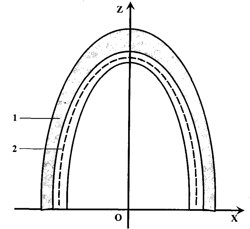
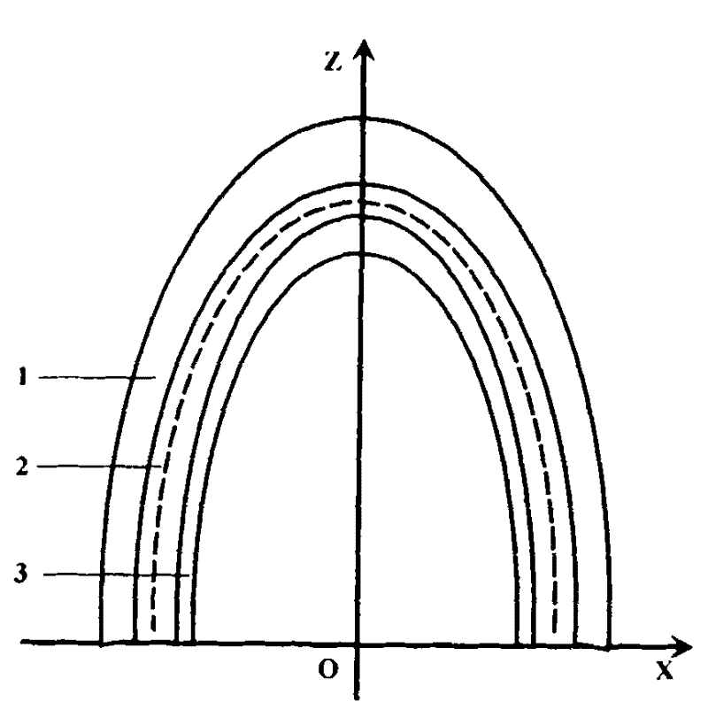
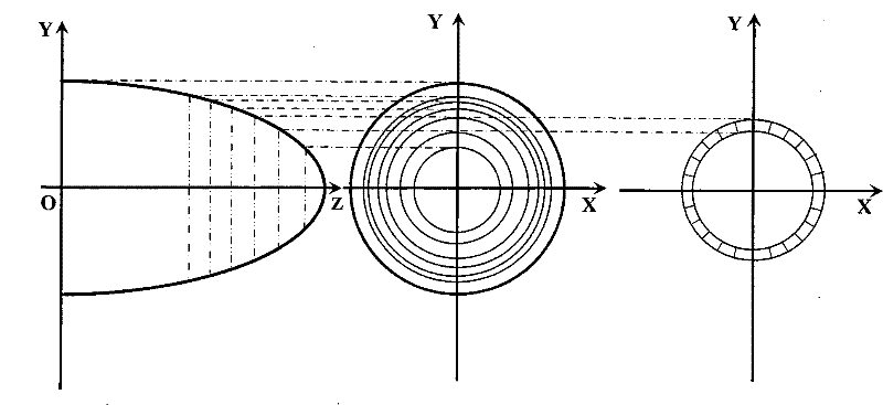
[0035] An electromagnetic shielding conformal optical window with a latitude and longitude grid structure, comprising a conformal optical window housing 1, ① making a latitude and longitude metal grid 2 on the inner side of the conformal optical window housing 1, the latitude and longitude metal grid The grid 2 covers the inner surface of the conformal optical window housing 1 as a whole, or ②, on the inner surface of the conformal optical window housing 1, from the outside to the inside, the latitude and longitude metal grid 2 and the inner housing 3 of the conformal optical window are sequentially fabricated , and the latitude and longitude metal grid 2 covers the inner surface of the conformal optical window housing 1 and the outer surface of the conformal optical window inner housing 3 as a whole; The metal wefts are uniformly arranged at equal central...


PUM


Abstract

The invention provides an electromagnetic shielding conformal optical window with a longitude and latitude-shaped mesh structure, which belongs to the technical field of electromagnetic shielding of optical transparent pieces. The electromagnetic shielding conformal optical window comprises a conformal optical window and is characterized in that: (1) a longitude and latitude-shaped metal mesh is manufactured on the inner side surface of the conformal optical window shell; and the longitude and latitude-shaped metal mesh covers the whole inner side surface of the conformal optical window shell; or (2) a longitude and latitude-shaped metal mesh and a conformal optical window inner shell are manufactured on the inner surface of the conformal optical window shell from outside to inside in turn; the longitude and latitude-shaped metal mesh covers the whole inner surface of the conformal optical window shell and outer surface of the conformal optical window inner shell; the latitude-shaped metal mesh consists of metal longitudes and metal latitudes; the metal latitudes are uniformly arranged in an equivalent centre angle along a circumferential direction; the metal longitudes are arranged at equal intervals according to a metal mesh cycle along a generatrix direction; and the metal longitudes and the metal latitudes are electrically connected with one another. The electromagnetic shielding conformal optical window with the longitude and latitude-shaped mesh structure is suitable for electromagnetic shielding technology of military or civil conformal optical windows for remote measuring and sensing, medical diagnosis, secret communication, aerospace equipment and the like.

Description

technical field [0001] The invention belongs to the technical field of electromagnetic shielding of optically transparent parts such as telemetry and remote sensing, medical diagnosis, secure communication, and aerospace equipment, and particularly relates to an electromagnetic shielding conformal optical window with a latitude and longitude grid structure. Background technique [0002] Precision Conformal Optics Technology (Precision Conformal Optics Technology) is based on the principle of aerodynamics. It breaks the current situation that traditional optical windows are mainly flat and hemispherical. It adopts aspheric surface technology to optimize the design of optical window surface, reducing air resistance and increasing flight speed. ; Raytheon, a research member of precision conformal optics, obtained the international patent "General asphere-conic conformal optical windows" of "conformal optics" in 1999, patent number WO 99 / 38033. [0003] With the increasingly com...

Claims


Application Information

Patent Timeline
Patent Type & Authority Patents(China)
IPC IPC(8): H05K9/00
Inventor 谭久彬刘永猛
Owner HARBIN INST OF TECH
Learn More