
Distillation device

A technology of distillation equipment and pipelines, which is applied in the field of distillation equipment and can solve problems such as efficiency that needs to be greatly improved.

Inactive Publication Date: 2010-12-15
伊夫林·乔斯特 +1
View PDF6 Cites 0 Cited by
  • Summary
  • Abstract
  • Description
  • Claims
  • Application Information

AI Technical Summary

Problems solved by technology

In particular, the efficiency of these distillation equipment needs to be greatly improved

Method used


Image

  • Distillation device
  • Distillation device
  • Distillation device

Examples


Embodiment Construction

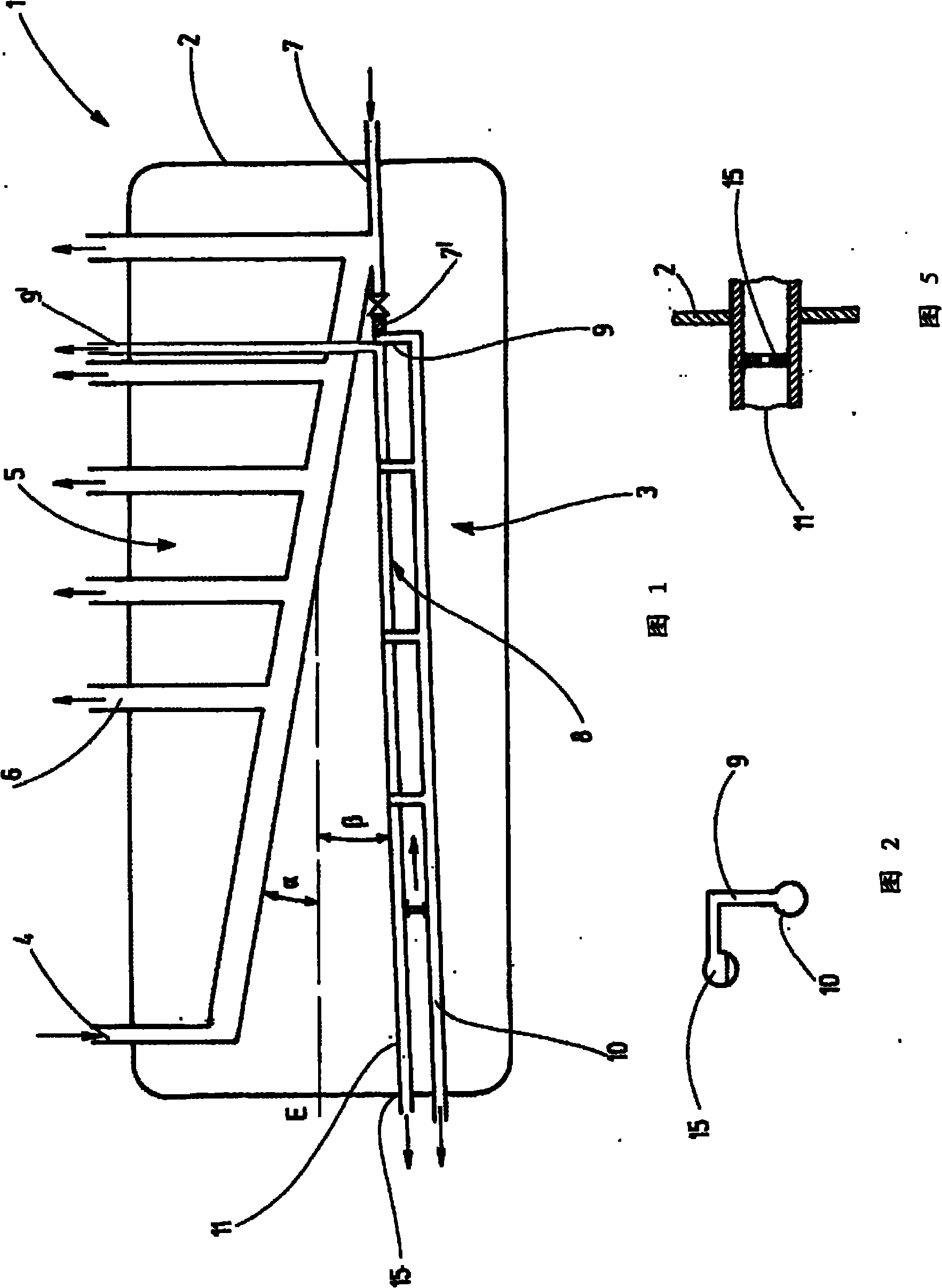
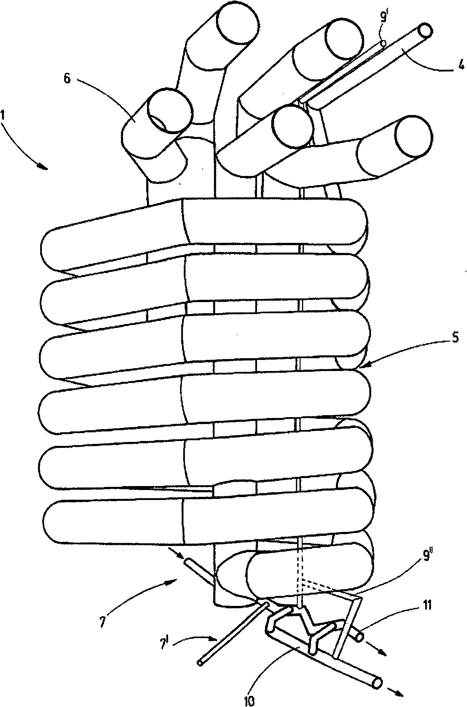
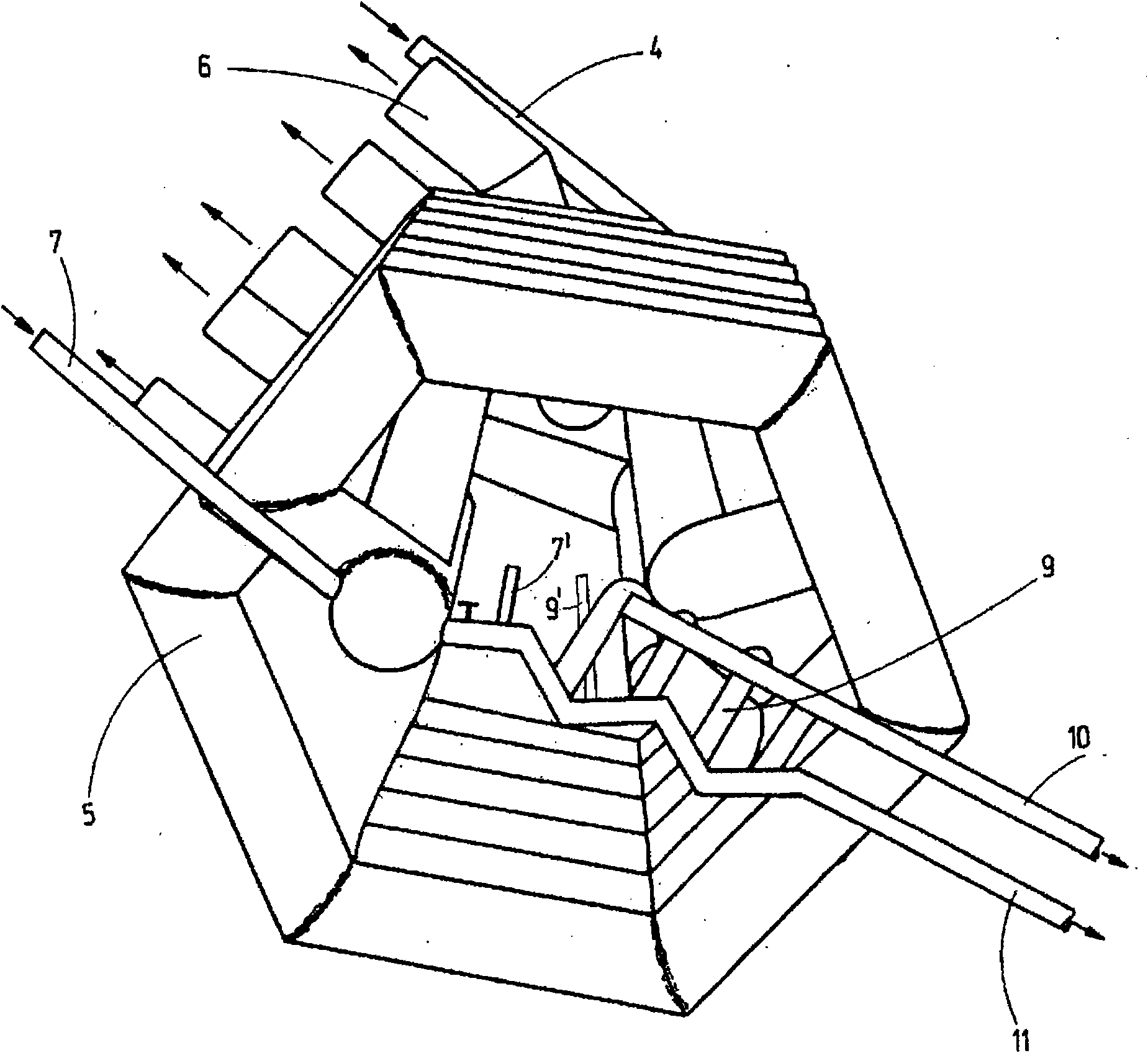
[0035] The distillation plant 1 has a container 2 which can be heated by means of a heating device (not shown in more detail), in this example by steam which is formed in a separately formed boiler and introduced into the container 2 , and the distillation plant 1 also has a line arrangement arranged in the vessel 2, wherein, for the line arrangement 3, a plurality of supply and treatment lines lead into or lead out of the vessel 2 (as the case may be). The container 2 has a pressure-resistant design and is well insulated. The piping set 3 in this example is composed of a copper pipe having excellent heat conductivity.

[0036]The line arrangement 3 has: a distillation medium inlet line 4 into the container 2; a continuous line of helical design forming a first distillation section 5 with a significantly larger diameter than the inlet line 4; various first A gas outlet line 6 branching from the first distillation section 5 with a diameter corresponding to the helical line, he...


PUM


Abstract

The invention relates to a distillation device (1), comprising at least one first distillation region (5) with at least one first gas outlet line (6), at least one second distillation region (8) with at least one further gas outlet line (9, 9'), wherein the distillation regions (5, 8) are connected to each other. The first distillation region (5) is formed by a first line, the second distillation region (8) by a second line, and both lines forming the distillation regions (5, 8) are connected to each other in a controllable way. The invention further relates to methods for operating such a distillation device (1).

Description

technical field [0001] The invention relates to a distillation apparatus for distilling off liquids, in particular for separating liquid mixtures. Background technique [0002] DE 1 773 893 A discloses a multistage distillation apparatus with a first evaporation vessel and a distillation column arranged on this vessel, an adjoining condenser and also with a further evaporation vessel and an associated condenser, wherein in In each case, these condensers were connected to subsequent evaporation vessels, and the condenser of the last vessel had a drain. In this case, all further evaporation vessels are arranged annularly around the distillation column, and the lines leading from the evaporation vessels to the condenser extend into the distillation column. Each evaporation vessel can be heated electrically. [0003] From WO 98 / 11395 A1 a heat exchanger is known, in which there are provided steam outlets for the steam generated in the heat exchanger, these steam outlets leadin...

Claims


Application Information

Patent Timeline
Patent Type & Authority Applications(China)
IPC IPC(8): B01D1/14B01D3/34
CPCB01D3/34B01D1/14
Inventor 伊夫林·乔斯特弗兰克·齐尔曼
Owner 伊夫林·乔斯特
Learn More