
Optical waveguide type wavelength dispersion compensation device and method for manufacturing the same

一种波长色散、色散补偿的技术,应用在光导、光学元件、仪器等方向,能够解决色散补偿特性存在极限、空间变大、制造困难等问题,达到优异色散补偿特性、色散补偿特性广、设置空间小的效果

Inactive Publication Date: 2010-12-15
FUJIKURA LTD
View PDF6 Cites 2 Cited by
  • Summary
  • Abstract
  • Description
  • Claims
  • Application Information

AI Technical Summary

Problems solved by technology

[0020] 1: Dispersion compensation using DCF requires a larger space due to the use of longer optical fibers, making it difficult to miniaturize
Furthermore, there is a limit to the dispersion compensation characteristics that can be achieved
[0021] 2: There is a limit to the dispersion compensation characteristics that can be achieved using FBG's dispersion compensation
[0022] 3: There is a limit to the dispersion compensation characteristics that can be achieved by using the coincident dispersion compensation of FBG
[0024] 5: Using AWG PLC, the structure is complicated, the manufacturing is difficult, and the cost becomes higher
In addition, a large space is required, and it is difficult to miniaturize the device
[0025] 6: The structure of the VIPA type dispersion compensator is complicated, the manufacture is difficult, and the cost becomes high

Method used


Image

  • Optical waveguide type wavelength dispersion compensation device and method for manufacturing the same
  • Optical waveguide type wavelength dispersion compensation device and method for manufacturing the same
  • Optical waveguide type wavelength dispersion compensation device and method for manufacturing the same

Examples


Embodiment 1

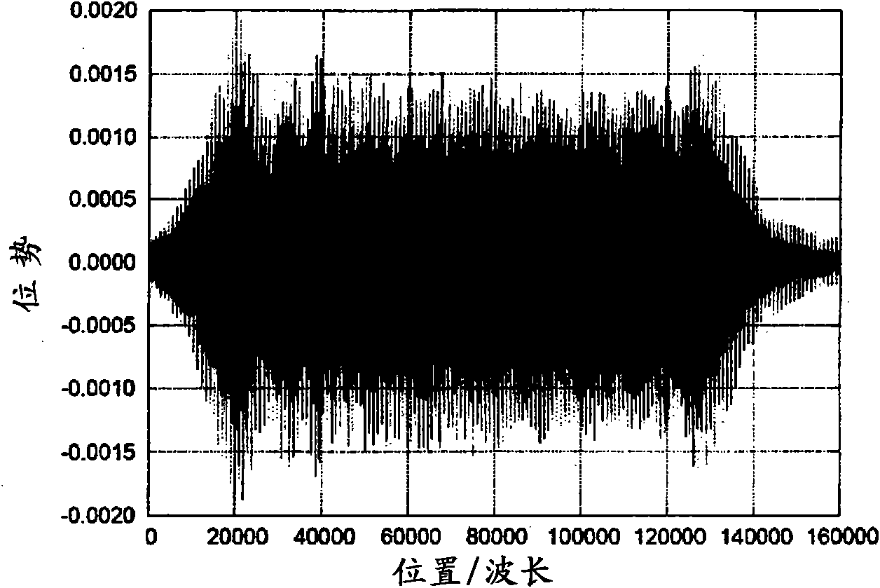
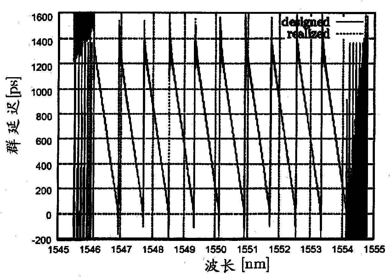
[0192] Designed in the wavelength region [1546.12nm~1554.13nm], the dispersion amount D=-1700ps / nm, the ratio of dispersion slope to dispersion RDS=0.0034nm -1 A dispersion compensation device for compensation of wavelength dispersion. At this time, the NPWG is designed so that the wavelength region for dispersion compensation is divided into 10 channels whose frequency f satisfies 193.4+0.1nTHz≤f≤193.5+0.1nTHz. Here, n represents an integer satisfying -5≤n≤4. The dispersion compensation device performs dispersion compensation in each channel. At this time, as described later Figure 29 As shown, there is a wavelength dependence in which the loss increases as the wavelength becomes shorter in each channel. Therefore, in this embodiment, in order to reduce the wavelength dependence, the wavelength dependence in which the loss increases as the wavelength becomes longer in each channel is added to the design range of the NPWG. At this time, it is designed so that the maximum ...

Embodiment 2

[0200] Designed in the wavelength region [1546.12nm~1554.13nm], the dispersion amount D=-1700ps / nm, the ratio of dispersion slope to dispersion RDS=0.0034nm -1 A dispersion compensation device for compensation of wavelength dispersion. At this time, the NPWG is designed so that the wavelength region for dispersion compensation is divided into 10 channels whose frequency f satisfies 193.4+0.1nTHz≤f≤193.5+0.1nTHz. Here, n represents an integer satisfying -5≤n≤4. The dispersion compensation device performs dispersion compensation in each channel. At this time, as described later Figure 35 As shown, there is a wavelength dependence in which the loss increases as the wavelength becomes shorter in each channel. Therefore, in this embodiment, in order to be able to reduce this wavelength dependence, the wavelength dependence that the loss increases as the wavelength becomes longer in each channel is added to the design spectrum of the NPWG. In this case, design so that the maxim...

Embodiment 3

[0208] Designed in the wavelength region [1546.12nm~1554.13nm], the dispersion amount D=-1700ps / nm, the ratio of dispersion slope to dispersion RDS=0.0034nm -1 A dispersion compensation device for compensation of wavelength dispersion. At this time, the NPWG is designed so that the wavelength region for dispersion compensation is divided into 10 channels whose frequency f satisfies 193.4+0.1nTHz≤f≤193.5+0.1nTHz. Here, n represents an integer satisfying -5≤n≤4. The dispersion compensation device performs dispersion compensation in each channel. At this time, as described later Figure 41 As shown, there is a wavelength dependence in which the loss increases as the wavelength becomes shorter in each channel. Therefore, in this embodiment, in order to be able to reduce this wavelength dependence, the wavelength dependence in which the loss increases as the wavelength becomes longer in each channel is added to the design spectrum of the NPWG. In this case, design so that the m...


PUM


Abstract

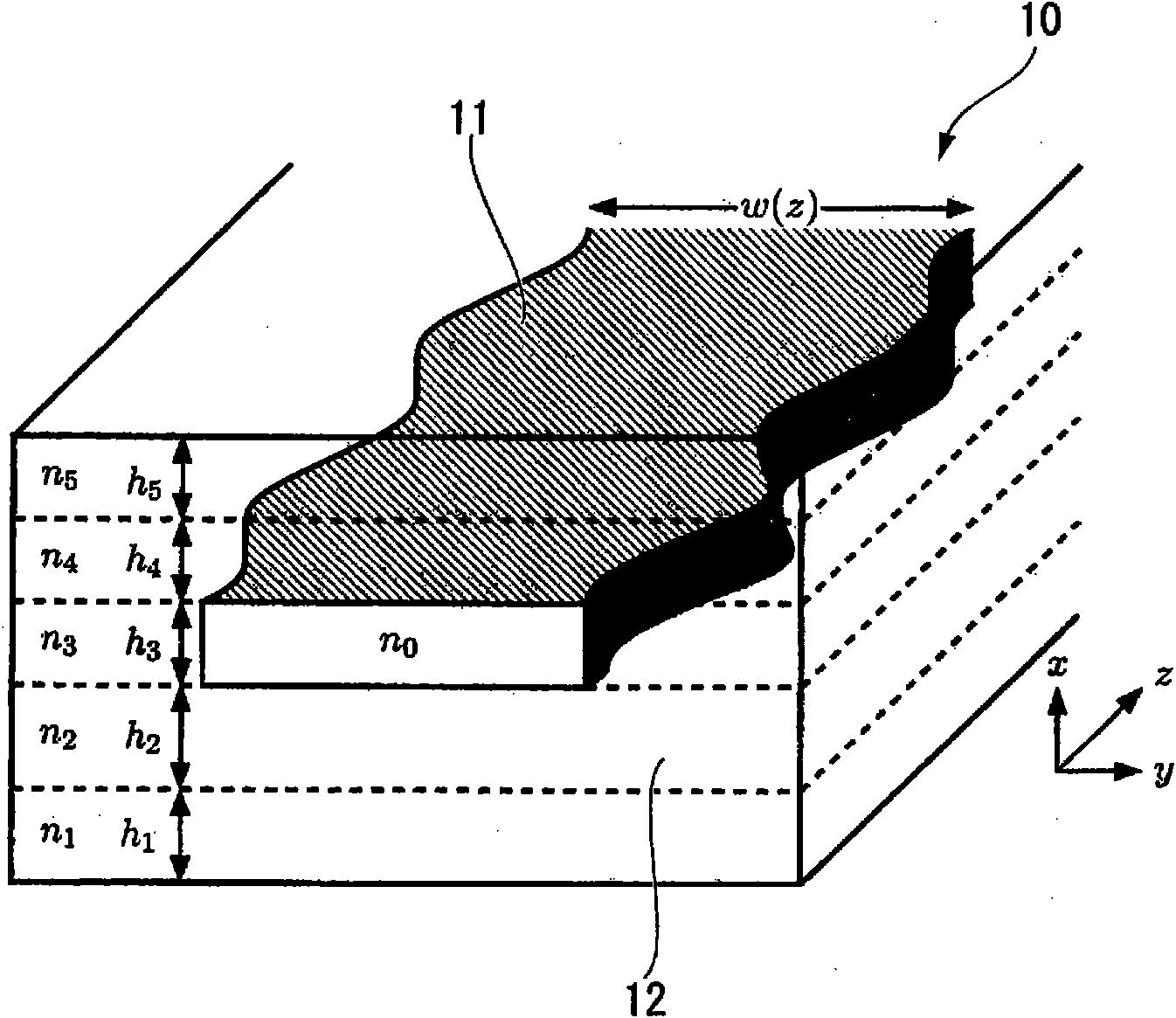
An optical waveguide type wavelength dispersion compensation device has an optical waveguide as a reflection type wavelength dispersion compensation means in which an equipment refraction index of a core changes unevenly over a light transmitting direction by changing a physical size of the core embedded in a clad. The core is designed in the following: (a) first, a first desired reflection spectrum is set with transmission losses neglected and an optical wavelength possible to compensate wavelength dispersion of an optical fiber to be compensated is then designed; (b) a wavelength dependency characteristic of a transmission loss in this optical waveguide is derived from an effective length of the optical waveguide designed in the process (a); and (c) next, a reverse dependency characteristic of the wavelength dependency is added to the first reflection spectrum to correct a second reflection spectrum and an equivalent refraction index distribution of the optical waveguide designed in the process (a) is re-designed by using the second reflection spectrum.

Description

technical field [0001] The present invention relates to a small optical waveguide type wavelength dispersion compensating device for compensating the wavelength dispersion of optical fiber and its manufacturing method. The device can be applied in optical fiber communication network and the like. [0002] This application claims priority based on Patent Application No. 2007-331006 for which it applied in Japan on December 21, 2007, and takes in the content into this application. Background technique [0003] In optical communication, wide-band and high-speed transmission of high-density wavelength multiplexing (DWDM: Dense Wavelength-Division Multiplexing) is constantly developing. In order to perform high-speed transmission, it is desirable for the transmission line to have as small a wavelength dispersion as possible in the transmission band, and to suppress nonlinear effects, it is desirable to use an optical fiber with non-zero wavelength dispersion. However, optical f...

Claims


Application Information

Patent Timeline
Patent Type & Authority Applications(China)
IPC IPC(8): G02B6/122
CPCG02B6/124G02B6/12007G02B6/29394B05D5/061
Inventor 官宁小川宪介
Owner FUJIKURA LTD
Learn More