Electronic control device

An electronic control device, current technology, applied in transportation and packaging, electric steering mechanism, circuit or fluid pipeline, etc., can solve the problems of high cost, complexity, increase in the number of components, etc., and achieve high output and low cost Effect

Inactive Publication Date: 2010-12-22
MITSUBISHI ELECTRIC CORP
View PDF1 Cites 18 Cited by
  • Summary
  • Abstract
  • Description
  • Claims
  • Application Information

AI Technical Summary

Problems solved by technology

[0005] In the electronic control device disclosed in Patent Document 1, there is a problem that a power substrate loaded with semiconductor switching elements, a housing loaded with high-current devices, and a control substrate loaded with small-current devices are required respectively, and the number of devices increases, causing the device The large-scale, complex and high cost of

Method used


Image

  • Electronic control device
  • Electronic control device
  • Electronic control device

Examples


Embodiment approach 1

[0035] Hereinafter, each embodiment of the present invention will be described based on the drawings, but the same or corresponding components and locations will be described with the same reference numerals in each of the drawings.

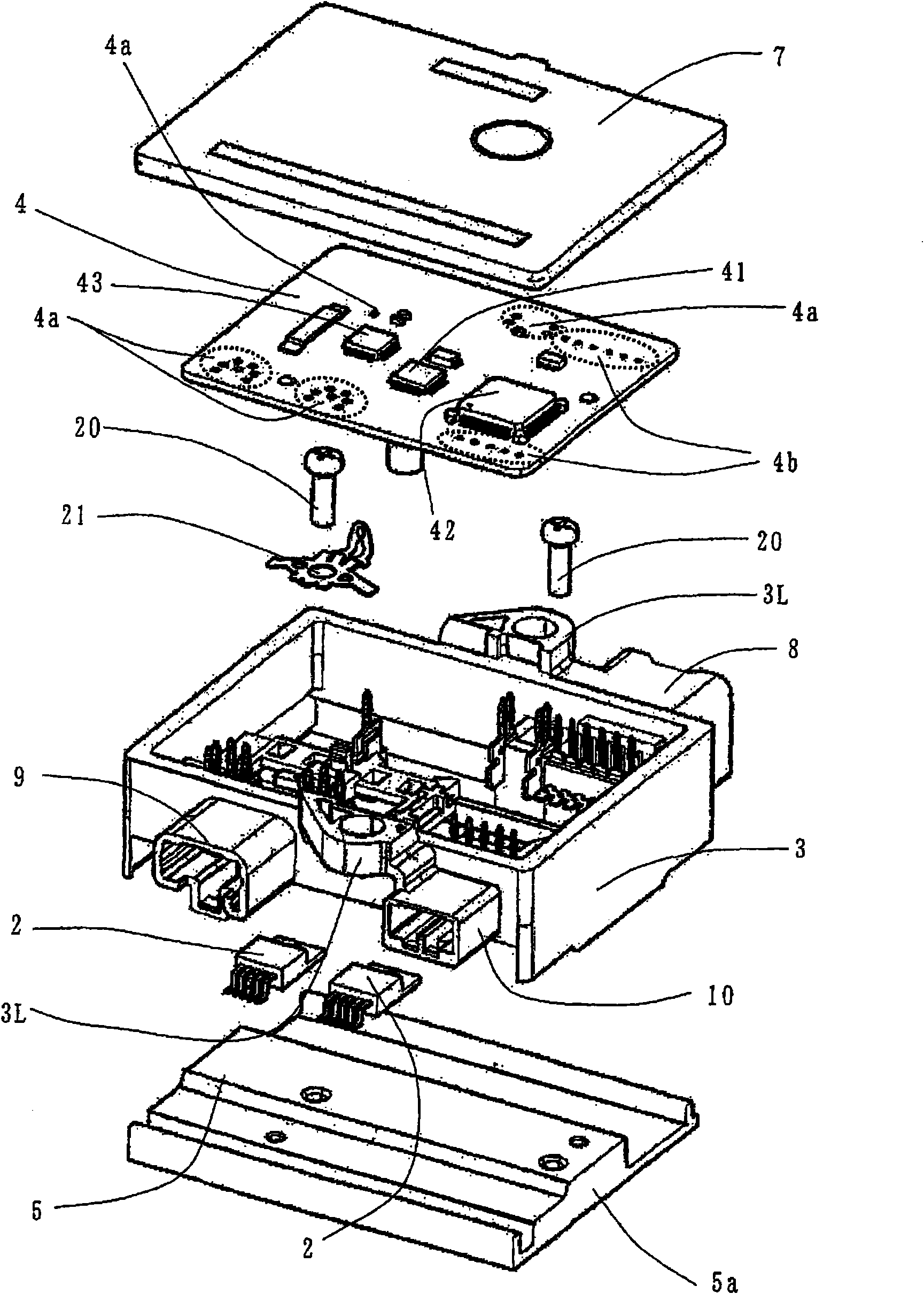
[0036] In this embodiment, an electronic control device 1 for an electric power steering device that assists a steering device of a vehicle by, for example, a rotational force of an electric motor will be described as an example.

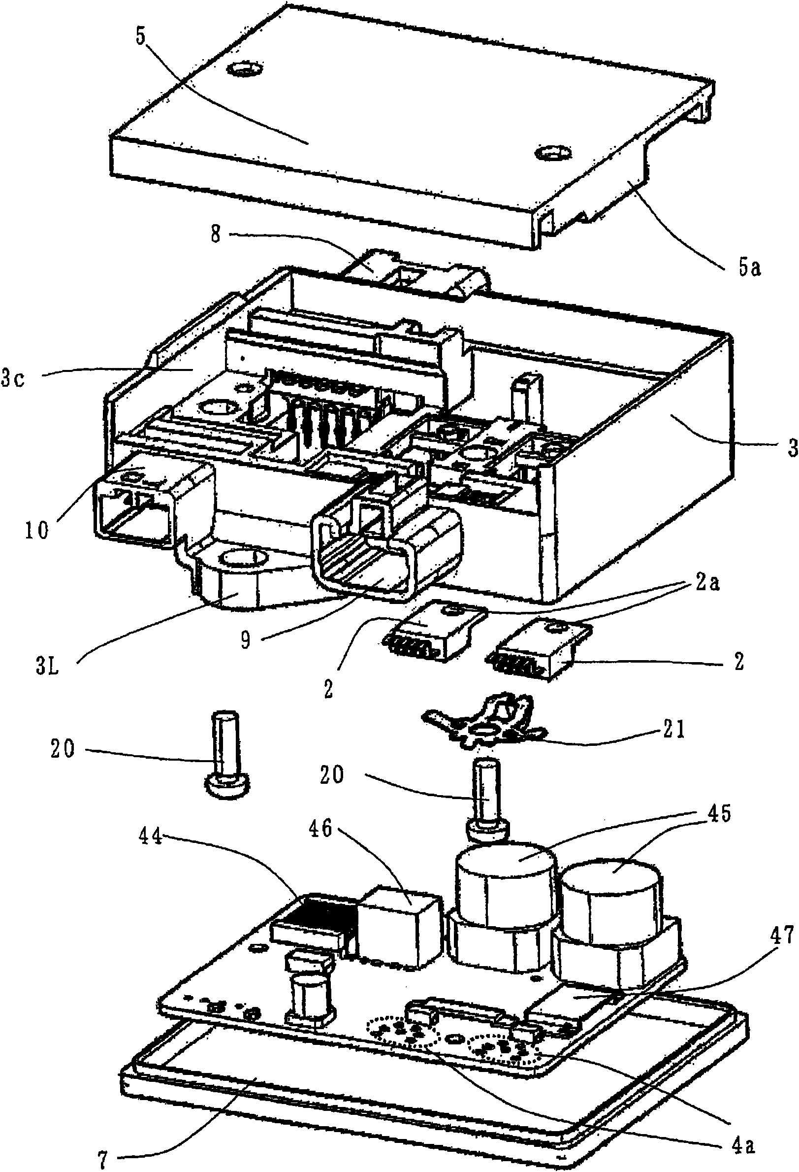
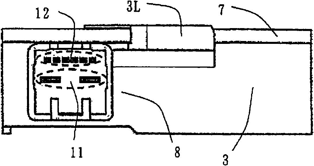
[0037] figure 1 It is an exploded perspective view showing the electronic control device 1 according to Embodiment 1 of the present invention; figure 2 viewed from the opposite direction figure 1 is an exploded perspective view showing an exploded perspective view of the electronic control device 1; image 3 yes means figure 1 A side view of the vehicle connector 8 side of the electronic control device 1; Figure 4 yes means figure 1 The side view of the motor connector 9 and the sensor connector 10 side of th...

Embodiment approach 2

[0167] Figure 21 It is a sectional view showing a main part of the electronic control device 1 according to Embodiment 2 of the present invention.

[0168] Figure 21 The electronic control unit 1 shown with Figure 15 The difference in the structure shown is that the capacitor 45 of the high-current device is in contact with the heat sink 5 through the intermediary 45a, and the microcomputer 41, the power supply IC 42 and the driver IC 43 of the small-current device are respectively connected to the cover plate 7 through the intermediary 41a, 42a, and 43a. touch.

[0169] Other structures are the same as those in Embodiment 1.

[0170] exist Figure 15 In the electronic control device 1 according to Embodiment 1 shown, the current device is in contact with the circuit board 4 only at the wiring pattern portion, and the surface of other current devices is exposed inside the casing formed by the case 3, the heat sink 5, and the cover plate 7. in the air.

[0171] Therefo...


PUM


Abstract

The invention provides an electronic control device possessing miniaturization, high output and long service life. The electronic control device comprises a housing (3) which is made from insulated resin and is provided with openings at two ends, an end part disposed at the housing (3), a radiator (5) of a semiconductor switch component (3) which is disposed at the surface of the housing (3), and a circuit substrate (4) which is disposed corresponding to the radiator (5). One surface of the circuit substrate (4) is provided with a plurality of low-current devices with microcomputers which control the driving of the semiconductor switch component (2), and the other surface is provided with a plurality of large-current devices with capacitors which absorbs the current wave flowing through the semiconductor switch component (2).

Description

technical field [0001] The present invention relates to an electronic control device for an electric power steering device for assisting a steering device of a vehicle by, for example, a rotational force of an electric motor. Background technique [0002] Conventionally, there is known an electronic control device in which semiconductor switching elements (FETs) as power devices are mounted on a metal substrate, and connecting members for electrically connecting the metal substrate to devices other than the metal substrate are mounted on the metal substrate. [0003] For example, the electronic control device disclosed in Patent Document 1 includes: a power substrate on which a bridge circuit composed of semiconductor switching elements for switching the electric current of the motor is mounted; The casing of the device; the control substrate loaded with small current devices such as a microcomputer; the connecting part that electrically connects the power substrate to the a...

Claims


Application Information

Patent Timeline
Patent Type & Authority Applications(China)
IPC IPC(8): B62D5/04
CPCB60R16/005B60R16/023F02N11/087F02N2011/0874H05K7/20509
Inventor 伊藤慎一富永努喜福隆之秋山周三谷川正明
Owner MITSUBISHI ELECTRIC CORP
Why Eureka
Try Eureka