Foil generating machine lead anode fly knife device

A lead anode, raw foil machine technology, applied in the electrolysis process, electroforming and other directions, can solve the problems of large volume, high processing cost, waste of energy, etc., and achieve the effect of small size, light structure, and ensuring continuity

Inactive Publication Date: 2010-12-22
XIAN AEROSPACE SOURCE POWER ENG CO LTD
View PDF3 Cites 4 Cited by
  • Summary
  • Abstract
  • Description
  • Claims
  • Application Information

AI Technical Summary

Problems solved by technology

[0012] In order to solve the technical problems of large volume, high processing cost and waste of energy in the existing foil machine lead anode flying knife device, the present invention provides a foil machine FPL lead anode flying knife device

Method used


Image

  • Foil generating machine lead anode fly knife device
  • Foil generating machine lead anode fly knife device
  • Foil generating machine lead anode fly knife device

Examples


Embodiment Construction

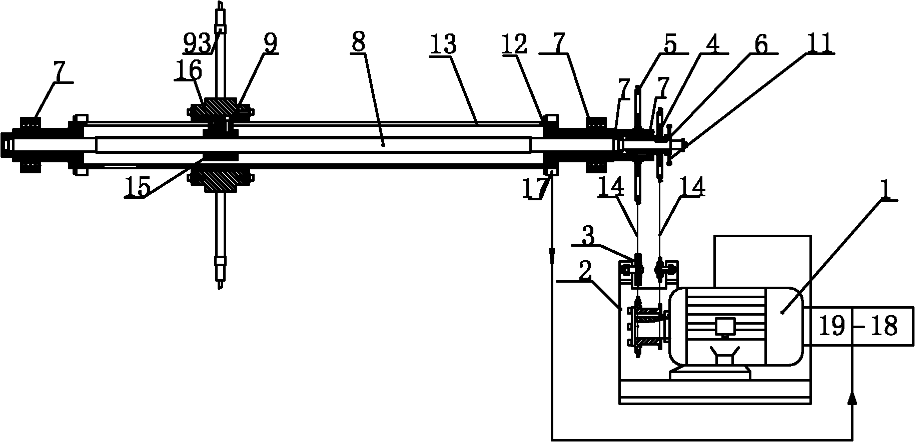
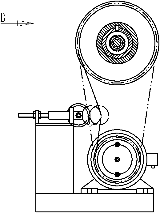
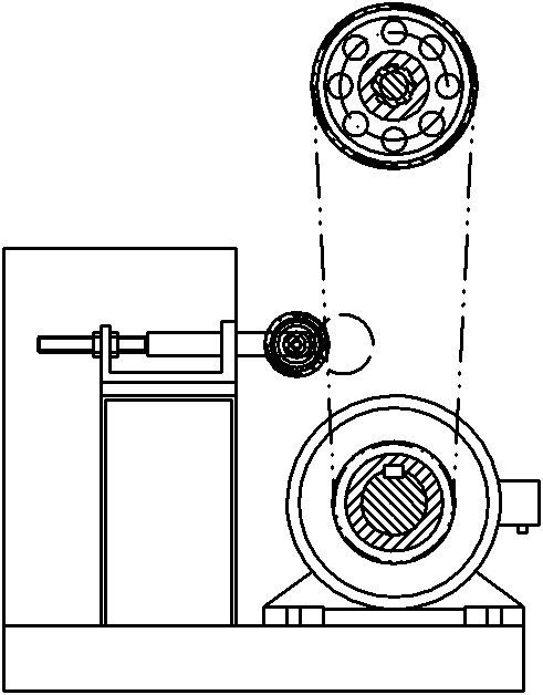
[0047] Such as figure 1 , figure 2 image 3 Shown is a schematic structural diagram of the lead anode flying knife device of the foil machine of the present invention, including a power source, a transmission assembly and a tool bar assembly. Output end; transmission assembly includes two main drive wheels 2, feed sprocket 4, rotating sprocket 5, rotating cylinder 12, rolling screw 8, rolling nut 15; rotating cylinder 12 is a hollow long cylinder, and its axial direction is provided with The feed groove 13 is supported by bearings at both ends; the rolling screw 8 is coaxially arranged in the rotating cylinder 12 and the two ends are respectively connected to the rotating cylinder 12 through the bearing 7; the rolling nut 15 can be driven by the rolling screw 8 The bottom moves axially along the rolling screw 8 in the rotating cylinder 12; the two main driving wheels 2 are fixed side by side on the output shaft of the power source; the feed sprocket 4 and the rotating sproc...


PUM


Abstract

The invention relates to a foil generating machine lead anode fly knife device comprising a power source, a drive assembly and a cutter bar assembly, wherein the drive assembly comprises two main driving wheels, a feeding chain wheel, a rotary chain wheel, a revolving drum, a rolling screw rod and a rolling nut. The invention solves the technical problem that the existing foil generating machine lead anode fly knife device has large volume, high processing cost and energy waste. The invention has the advantages of energy saving, small structure, convenient installation and long service life.

Description

technical field [0001] The invention relates to an anode flying knife device of a foil machine. Background technique [0002] In recent years, my country's electrolytic copper foil has developed rapidly. As the main raw material for printed circuit boards (PCB), the development of electrolytic copper foil has been following the development of circuit board (PCB) technology, and circuit boards (PCB) have followed the development of electronic products. With each passing day, electronic products are developing towards low cost, high reliability, high stability, and high functionality. As a result, newer and higher requirements are put forward for the performance and variety of electrolytic copper foil, which makes the development of electrolytic copper foil appear. a new development trend. Thickness develops in the direction of thin and ultra-thin. Common use of special performance copper foil. In order to improve the high reliability and high stability of electronic products...

Claims


Application Information

Patent Timeline
Patent Type & Authority Applications(China)
IPC IPC(8): C25D1/04
Inventor 李文孝叶鹏苏晓红
Owner XIAN AEROSPACE SOURCE POWER ENG CO LTD
Why Eureka
Try Eureka