Water flow vibration generator

A vibrating generator and water flow technology, applied in ocean energy power generation, engine components, machines/engines, etc., can solve the problem of not making full use of the energy of rivers, ditches and shallow water currents, and achieve the effect of reducing maintenance costs

Inactive Publication Date: 2012-03-21
NANJING UNIV OF AERONAUTICS & ASTRONAUTICS
View PDF0 Cites 0 Cited by
  • Summary
  • Abstract
  • Description
  • Claims
  • Application Information

AI Technical Summary

Problems solved by technology

[0003] The purpose of the present invention is to provide a water flow vibration generator to overcome the deficiency that the existing power generation method cannot fully utilize the water flow energy in rivers, ditches and shallow seas

Method used


Image

  • Water flow vibration generator
  • Water flow vibration generator
  • Water flow vibration generator

Examples


Embodiment 1

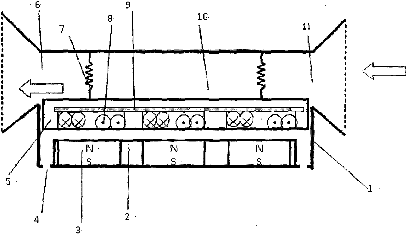
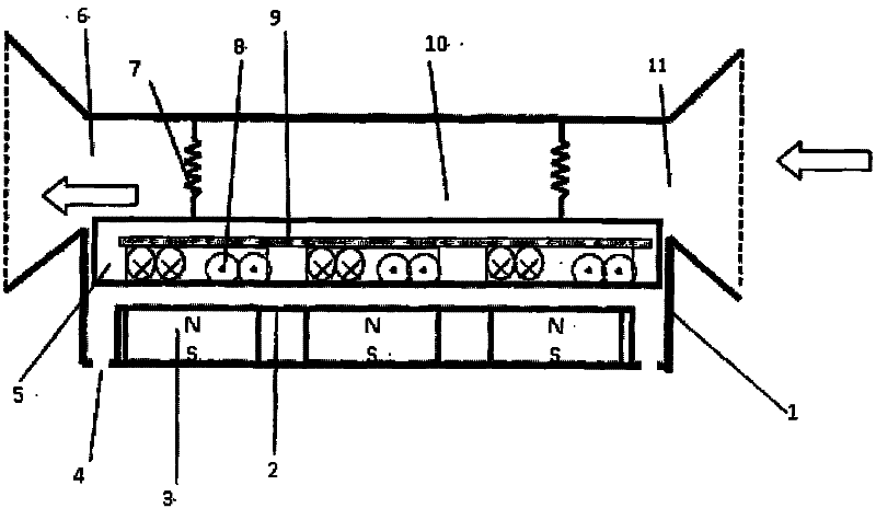
[0017] The vibration generator of embodiment 1 is as figure 1 shown.

[0018] The generator includes a box body 1, a water inlet 11, a water outlet 6, a sealed coil box 5, a coil group 8, a sealed permanent magnet box 2, a permanent magnet group 3, and a parallel spring 7, wherein the coil group 5 is fixed on the sealed coil box 5 In the middle; the permanent magnet group 3 is fixed in the sealed permanent magnet box 4; the upper part of the parallel spring 7 is connected with the top of the casing, and the lower part is connected with the sealed coil box 5; the sealed permanent magnet box 2 is located directly below the sealed coil box 5, It is fixed on the bottom surface of the box; there is a gap between the permanent magnet box and the coil box; the length and width of the coil box are slightly smaller than the length and width of the box, and the length and width of the permanent magnet box are smaller than the length and width of the coil box; the coil Facing the perma...

Embodiment 2

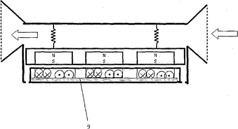
[0021] The piezoelectric generator of embodiment 2 is as figure 2 shown.

[0022] The generator includes a box body 1, a water inlet 11, a water outlet 6, a sealed coil box 5, a coil group 8, a sealed permanent magnet box 2, a permanent magnet group 3, and a parallel spring 7, wherein the coil group 5 is fixed on the sealed coil box 5 Middle; the permanent magnet group 3 is fixed in the sealed permanent magnet box 4; the upper part of the parallel spring 7 is connected to the top of the box body, and the lower part is connected to the sealed permanent magnet box 5; the sealed coil box 5 is located directly below the sealed permanent magnet box 4 , fixed on the bottom surface of the box; there is a gap between the sealed permanent magnet box and the sealed coil box; the length and width of the sealed permanent magnet box 4 are slightly smaller than the length and width of the box body, and the length and width of the sealed coil box are smaller than the sealed permanent magnet...


PUM


Abstract

The invention relates to a water flow vibration generator and belongs to the technical field of vibration power generation. The water flow vibration generator comprises a box body (1), a sealed coil case (5) which is arranged inside the box body and a sealed permanent magnet case (2), wherein a coil group (8) is arranged inside the sealed coil case (5); a permanent magnet group (3) is arranged inside the sealed permanent magnet case (2); one box of the sealed coil case (5) and the sealed permanent magnet case (2) is arranged at the bottom of the box body (1) to serve as a stator in a fixed state, and the other box is connected with the top of the box body of a parallel spring (7) to serve as a vibrator in a suspended state. A movable gap is reserved between the vibrator and the periphery of the box body and the stator; the coil group (8) is opposite to the direction of the permanent magnet group (3); and a water inlet (11) and a water outlet (6) are formed on the box body (1), and arepositioned on the upper parts of two opposite side surfaces of the box body. The water flow vibration generator can generate power by fully utilizing water flow energy in rivers, ditches and shallow seas.

Description

technical field [0001] The invention relates to a water flow vibration generator, which belongs to the technical field of vibration power generation. Background technique [0002] In existing hydroelectric power generation technology, it is necessary to build a reservoir and use a generator with a water turbine. Among the existing tidal power generation technologies, the tidal dam (Tidal Barrage) technology needs to build a reservoir and use a generator with a water turbine; while the tidal stream (Tidal streams) technology uses an underwater generator with a water turbine. In wave power generation technology, it is necessary to build a reservoir (TAPCHAN gradient channel wave capacity conversion method) or a closed cavity (OWC oscillating air column method) and use a generator with a water turbine or a steam turbine. Due to the need to build water storage units and use rotating parts, these technologies are not suitable for harvesting energy from currents in rivers, ditche...

Claims


Application Information

Patent Timeline
Patent Type & Authority Patents(China)
IPC IPC(8): F03B13/00F03B13/14H02K35/00
CPCY02E10/38Y02E10/30
Inventor 胡俊辉李华峰赵淳生
Owner NANJING UNIV OF AERONAUTICS & ASTRONAUTICS
Why Eureka
Try Eureka