Piezoelectric lighter for preventing children from using

A lighter and piezoelectric technology, applied in the direction of igniter with fuel, combustion ignition, combustion method, etc., can solve the problems of complex structure of lighter, complicated operation, increased manufacturing cost of lighter, etc.

Inactive Publication Date: 2010-12-22
李建义
View PDF10 Cites 1 Cited by
  • Summary
  • Abstract
  • Description
  • Claims
  • Application Information

AI Technical Summary

Problems solved by technology

[0006] There are already many methods in the prior art to prevent piezoelectric lighters from being misused by children, but the lighters in the prior art either complicate the structure of the lighter, or have too many parts that ...

Method used


Image

  • Piezoelectric lighter for preventing children from using
  • Piezoelectric lighter for preventing children from using
  • Piezoelectric lighter for preventing children from using

Examples


Embodiment 1

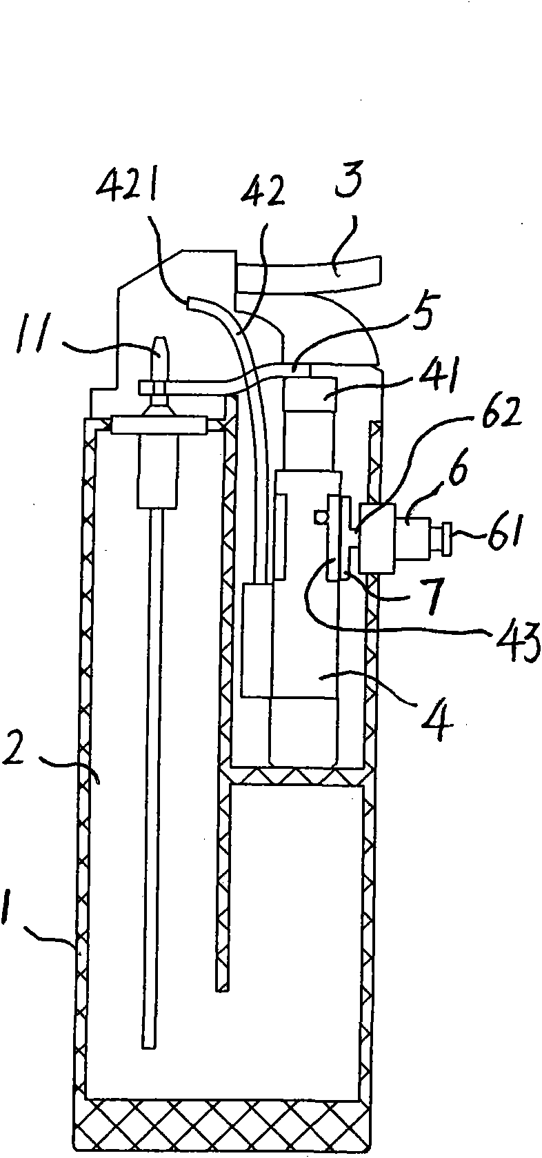
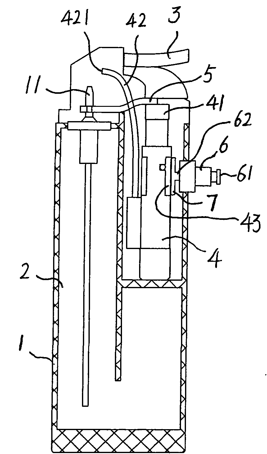
[0014] Embodiment 1: as figure 1 As shown, this embodiment includes a housing 1, a gas tank 2, a button 3 and a piezoelectric ignition device 4, the gas tank 1 is provided with an air outlet nozzle 11, the button 3 is arranged at one end of the conductive head 41 of the piezoelectric ignition device 4, and the button 3 A metal seesaw 5 is arranged between one side and the air outlet nozzle 11, and one end of the metal seesaw 5 is stuck on the air outlet nozzle 11, and the other end is placed between the button 3 and the conductive head 41 of the piezoelectric ignition device 4, and the piezoelectric ignition device 4 Lead out the ignition wire 42, the lead-out end 421 of the ignition wire 42 stretches out near the gas outlet nozzle 11, and a button switch 6 is also provided on the lighter housing 1, and the button switch 6 is provided with a switch button 61 that can move The moving part 62, the moving part 62 is fixedly connected with the blocking part 7, the blocking part 7 ...

Embodiment 2

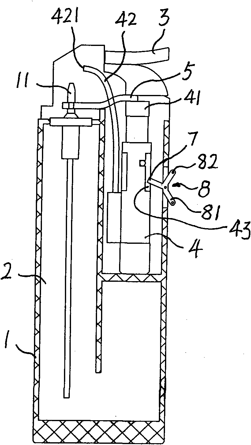
[0015] Embodiment 2: as figure 2 As shown, this embodiment includes a housing 1, a gas tank 2, a button 3 and a piezoelectric ignition device 4, the gas tank 1 is provided with an air outlet nozzle 11, the button 3 is arranged at one end of the conductive head 41 of the piezoelectric ignition device 4, and the button 3 A metal seesaw 5 is arranged between one side and the air outlet nozzle 11, and one end of the metal seesaw 5 is stuck on the air outlet nozzle 11, and the other end is placed between the button 3 and the conductive head 41 of the piezoelectric ignition device 4, and the piezoelectric ignition device 4 Lead out the ignition wire 42, the lead-out end 421 of the ignition wire 42 protrudes near the outlet nozzle 11, and the joystick 8 is hinged near the head bump guide rail 43 of the piezoelectric ignition device on the lighter housing 1, and the joystick 8 A part extends into the position of the lighter housing 1 facing the piezoelectric ignition device 4 to hit ...


PUM


Abstract

The invention relates to a piezoelectric lighter for preventing children from using, comprising a shell, a gas tank, a press-button and a piezoelectric ignition device, wherein the gas tank is provided with an outgassing nozzle; the press-button is arranged at one end of the conductive head of the piezoelectric ignition device; an interlock is arranged between one side of the press-button side and the outgassing nozzle; an ignition wire is leaded out of the piezoelectric ignition device; and the leading-out terminal of the ignition wire extends nearby the outgassing nozzle. In the technical scheme of the invention, a barrier piece is arranged, which can enters into and breaks way from the pounding head lug guide rail on the piezoelectric ignition device. The obstruction of the barrier piece leads the pounding head of the piezoelectric ignition device not to beat piezoelectric ceramics to stop the discharge process, thereby achieving the purpose of preventing the children from using. The invention has the advantages of simple structure, low manufacturing cost and convenient use.

Description

Technical field [0001] The invention relates to a piezoelectric lighter which is child-resistant. Background technique [0002] The piezoelectric lighter referred to in the present invention refers to a lighter that includes a piezoelectric ignition device and uses the piezoelectric ignition device as a spark generating device for igniting lighter fuel. [0003] Existing piezoelectric lighters include a housing, a gas tank, a button and a piezoelectric ignition device. The gas tank is provided with an air outlet nozzle, the button is arranged at one end of the conductive head of the piezoelectric ignition device, and a linkage is provided between one side of the button and the outlet nozzle. device, the piezoelectric ignition device leads to an ignition wire, and the lead-out end of the wire stretches out near the gas outlet nozzle. [0004] At present, the structure of the piezoelectric ignition device commonly used in the market is disclosed in Chinese patent CN2791502. W...

Claims


Application Information

Patent Timeline
IPC IPC(8): F23Q2/34
Inventor 李建义
Owner 李建义
Why Eureka
Try Eureka