Novel foil winding type coil leading copper busbar

A technology of foil winding and coil, which is applied in the field of new foil winding coil lead-out copper bars, can solve the problems of large copper consumption and high production cost, and achieve the effect of small copper consumption and reduced production cost

Inactive Publication Date: 2010-12-22
SUZHOU IND PARK LONGSHENG ELECTRICAL EQUIP MFG
View PDF0 Cites 7 Cited by
  • Summary
  • Abstract
  • Description
  • Claims
  • Application Information

AI Technical Summary

Problems solved by technology

The advantage of this foil-wound coil lead-out copper bar structure is that it will not cause local overheating of the copper bar, but because the width of the welding part 1 of the copper bar inside the coil is wider, the copper consumption is larger and the production cost is higher.

Method used


Image

  • Novel foil winding type coil leading copper busbar
  • Novel foil winding type coil leading copper busbar
  • Novel foil winding type coil leading copper busbar

Examples


Embodiment Construction

[0020] Preferred embodiments of the present invention will be described in detail below in conjunction with accompanying drawing:

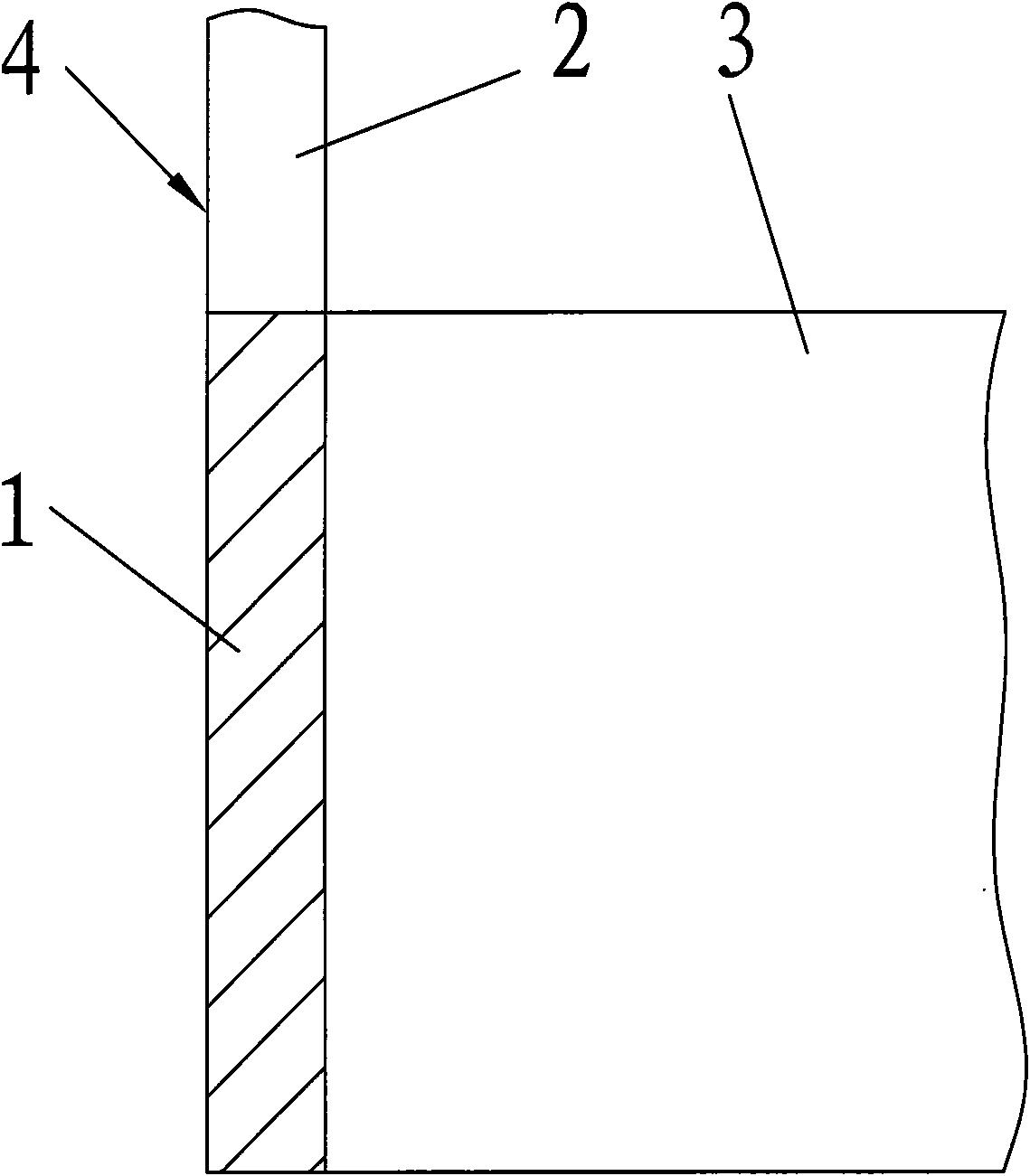
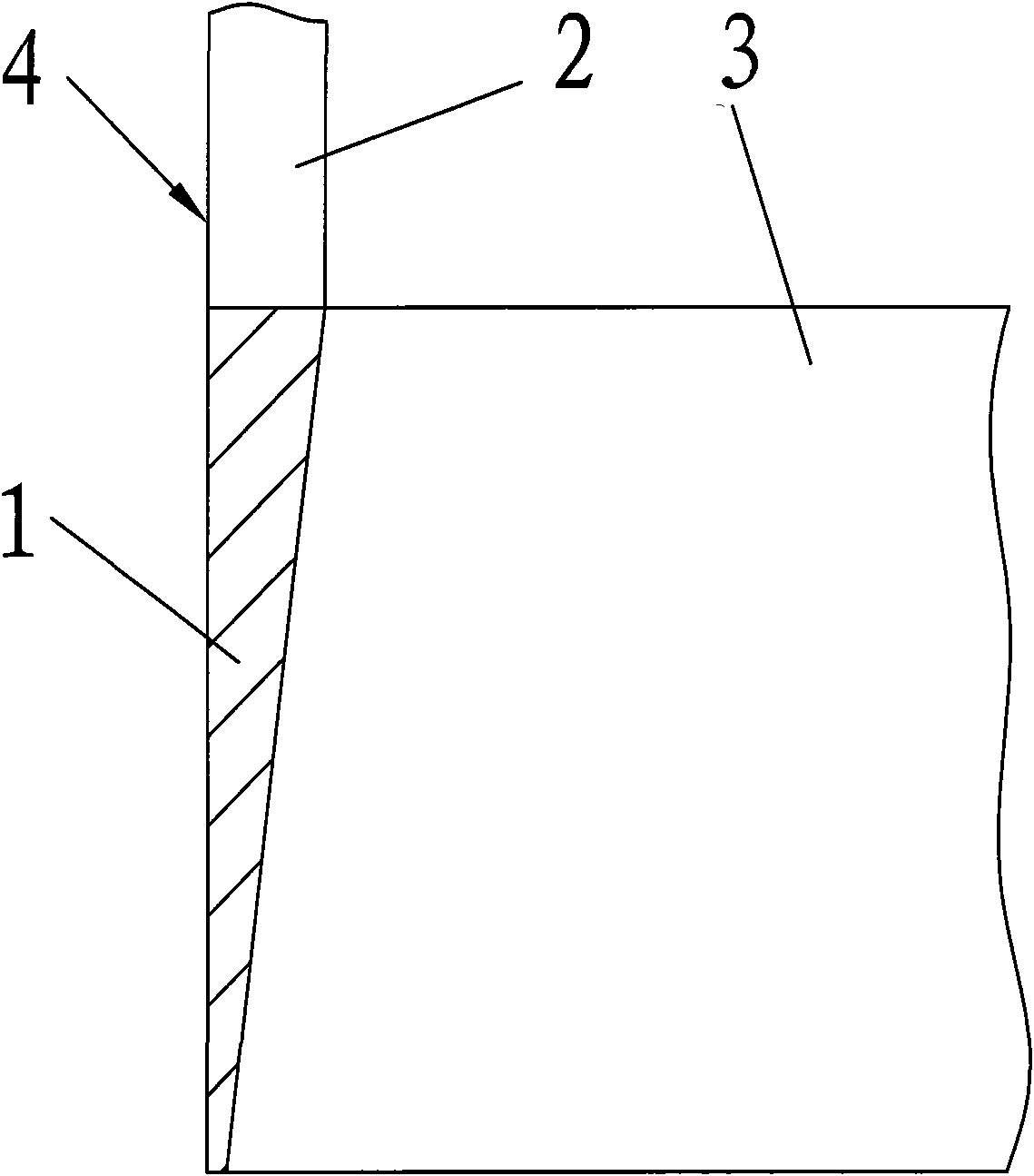
[0021] as attached image 3 And attached Figure 4 As shown in , a new foil-wound coil lead-out copper bar, the copper bar 4 includes a welding part 1 welded on the copper foil 3 and a lead-out part 2, and the width of the welding part 1 of the copper bar 4 decreases from top to bottom.

[0022] The welding part 1 of the copper bar 4 is an inverted right-angled trapezoid, or can be made into a right-angled triangle, and the lower end of the welding part has an end insulation 5 .

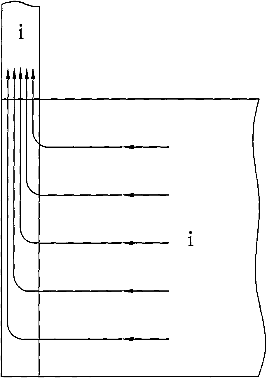
[0023] Tests have shown that compared with the traditional foil-wound coil lead-out copper bar structure, the current distribution in the lead-out bar of this lead-out copper bar structure is the same, and thus does not cause local overheating of the welding part 1 .

[0024] as attached Figure 7 As shown in , when making copper bars, the copper bars can be used on t...


PUM


Abstract

The invention relates to a novel foil winding type coil leading copper busbar. The copper busbar comprises a welding part welded on a copper foil and a leading part, wherein the width of the welding part of the copper busbar decreases from top to bottom, namely the welding part is an inverted right-angled trapezoid or a right angled triangle. Experiments show that the current distribution of the leading busbar of the leading copper busbar structure of the invention is uniform compared with the traditional winding type coil leading copper busbar structure, thus the local overheating of the welding part can not be caused. In addition, the amount of copper of the invention is about the half of that of the traditional structure while the width of the copper foil is ensured, thus the dosage of copper is low and the production cost can be greatly reduced.

Description

technical field [0001] The invention relates to a novel foil-wound coil lead-out copper bar. Background technique [0002] The traditional foil-wound coil lead-out copper bar structure, such as the attached figure 1 As shown, the cross-sectional width of the welding part 1 of the copper bar 4 and the copper foil 3 in the entire welding area is constant, which is a constant value, and the current distribution diagram in the lead-out bar is shown in the attached figure 2 shown. The advantage of this foil-wound coil lead-out copper bar structure is that it will not cause local overheating of the copper bar, but because the width of the welding part 1 of the copper bar inside the coil is relatively wide, the copper consumption is large and the production cost is high. Contents of the invention [0003] The purpose of the present invention is to provide a new type of foil-wound coil lead-out copper bar, which can not only save the amount of copper bar, but also ensure that t...

Claims


Application Information

Patent Timeline
Patent Type & Authority Applications(China)
IPC IPC(8): H01F27/29H01F41/10
Inventor 沈茂龙顾健钱建越王忠顺陶云生
Owner SUZHOU IND PARK LONGSHENG ELECTRICAL EQUIP MFG
Why Eureka
Try Eureka