Rotary transformer initial position signal autocorrection method

A technology of resolver and initial position, applied in the field of resolver, can solve problems such as increasing process and cost, and achieve the effects of improving measurement accuracy, eliminating measurement errors, and saving manual calibration costs

Active Publication Date: 2012-07-04
深蓝汽车科技有限公司
View PDF0 Cites 0 Cited by
  • Summary
  • Abstract
  • Description
  • Claims
  • Application Information

AI Technical Summary

Problems solved by technology

At present, the calibration methods of most motor factories use mechanical positioning pins or positioning notches, or use special equipment to calibrate the initial position of the resolver. These positioning methods increase the process and cost.

Method used


Image

  • Rotary transformer initial position signal autocorrection method
  • Rotary transformer initial position signal autocorrection method
  • Rotary transformer initial position signal autocorrection method

Examples


Embodiment Construction

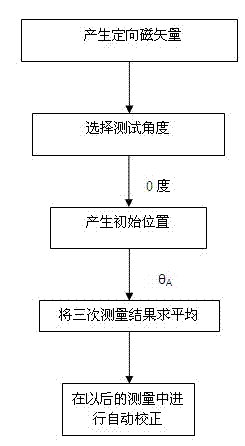
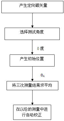
[0016] The technical solution of the present invention will be described in further detail below in conjunction with the accompanying drawings.

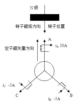
[0017] First, the stator magnetic vector with a fixed direction is generated according to the field-oriented control method; through the stator three-phase voltage setting, the motor stator A is connected to 10A, B is connected to -5A, and C is connected to -5A to generate an orientation that coincides with the stator A magnetic field;

[0018] Specific as figure 2 shown.

[0019] The stator generates a magnetic vector that coincides with the axis of the A-phase coil through magnetic field orientation, drags the rotor to a balanced position, and assumes that the electrical angle of the rotor position at this time is 0 degrees, and this value is the initial value of the test;

[0020] The resolver decoding chip AD1205 on the motor controller converts the resolver rotor absolute position value θ A Analyze it, and then transmit the ...


PUM


Abstract

The invention discloses a rotary transformer initial position signal autocorrection method, which realizes stator vector orientation through software, calculates the average value after multiple positions and multiple angles are tested. The method of the invention not only reduces the cost, but also improves the rotary transformer initial position signal autocorrection accuracy.

Description

technical field [0001] The invention belongs to the technical field of rotary transformers, in particular to detecting the initial position of a rotor of a permanent magnet synchronous motor, and in particular to a method for automatically correcting initial position signals of a rotary transformer. Background technique [0002] At present, permanent magnet synchronous motors are very suitable for electric vehicles and hybrid vehicle systems. The control requirements for permanent magnet synchronous motors are very precise. In permanent magnet synchronous control systems, not only the motors are required to work in various complex environments, but also for The control accuracy of the motor's angle, speed, and torque is very high, so it is required to detect and control the rotor position signal of the motor. [0003] In order to accurately detect the rotor position signal, the initial position correction must be performed when the resolver is installed. At present, the cal...

Claims


Application Information

Patent Timeline
Patent Type & Authority Patents(China)
IPC IPC(8): H02P21/00H02P6/16
Inventor 王璐肖伟薛山张正兴
Owner 深蓝汽车科技有限公司
Why Eureka
Try Eureka