Milling positioning tool for shaft sleeve

A technology for positioning tooling and milling, which is applied in the field of milling and positioning tooling for shaft sleeves, and can solve problems such as poor adjustment effect and long adjustment time

Inactive Publication Date: 2010-12-29
溧阳市虹翔机械制造有限公司
View PDF0 Cites 5 Cited by
  • Summary
  • Abstract
  • Description
  • Claims
  • Application Information

AI Technical Summary

Problems solved by technology

This method takes a long time to adj...

Method used


Image

  • Milling positioning tool for shaft sleeve
  • Milling positioning tool for shaft sleeve
  • Milling positioning tool for shaft sleeve

Examples


Embodiment Construction

[0017] The technical solution will be further described below in conjunction with the accompanying drawings and specific embodiments.

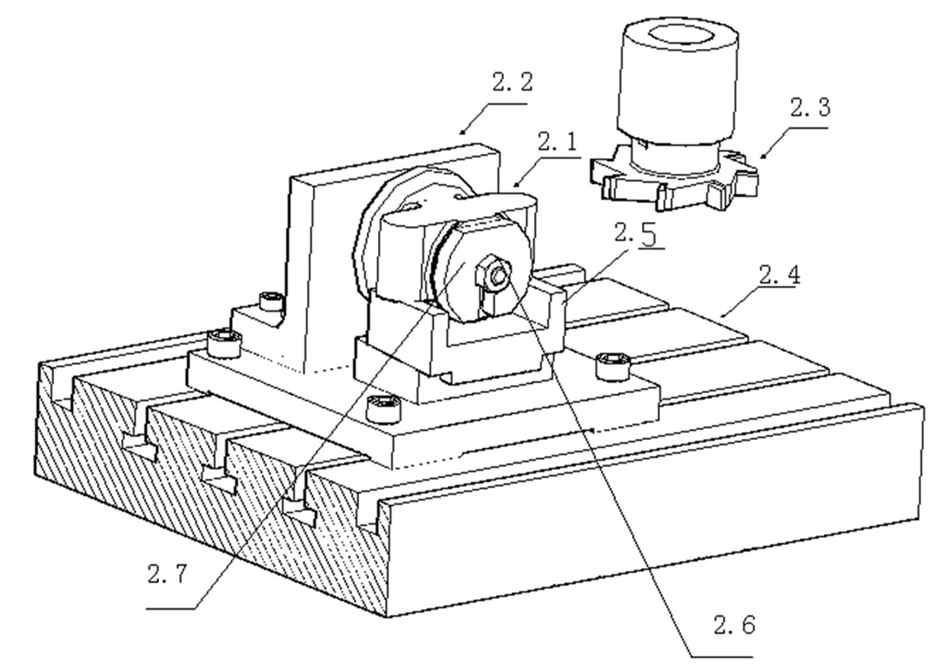
[0018] A milling positioning tool for a shaft sleeve, including an angle iron mandrel positioning seat 2.2, and an oblique plug iron 2.5; the oblique plug iron 2.5 includes upper and lower parts:

[0019] The bottom surface of the lower part 3.2 is horizontal, and the top surface is provided with inclined grooves;

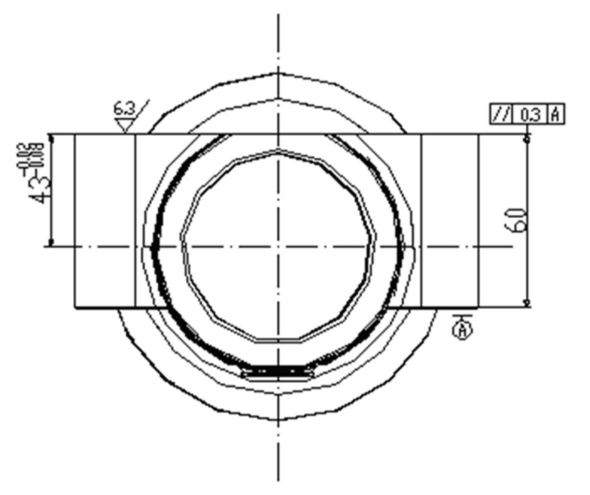
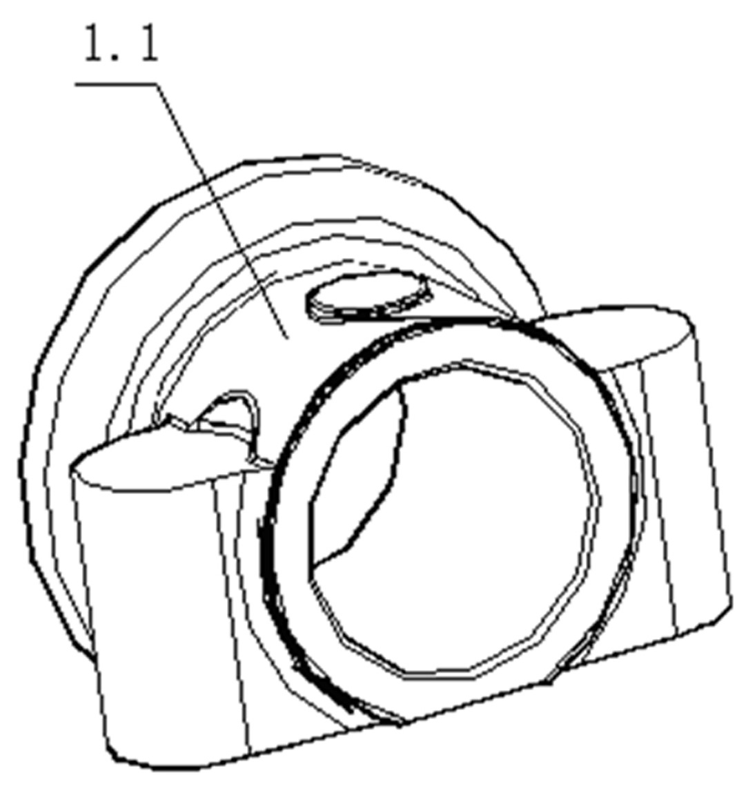
[0020] The top surface of the upper part 3.1 is provided with a horizontal groove, the width of the horizontal groove is not less than the width of the outer arc portion 1.1 of the processed bushing, and the depth of the horizontal groove is not smaller than the outer arc portion of the processed bushing 1.1 in height, the upper edge of the horizontal groove is horizontal;

[0021] The bottom surface of the upper part 3.1 is provided with an inclined protrusion corresponding to the inclined groove; the inclined protrusion slides i...


PUM

PropertyMeasurementUnit
Slopeaaaaaaaaaa

Abstract

The invention discloses a milling positioning tool for a shaft sleeve. The tool comprises an angle iron core rod positioning seat and an oblique filling iron, wherein the oblique filling iron comprises an upper part and a lower part; the bottom surface of the lower part is horizontal, while the top surface is provided with an oblique groove; the top surface of the upper part is provided with a horizontal groove, of which the width is not less than the width of a cambered part outside the machined shaft sleeve; the depth of the horizontal groove is not less than the height of the cambered part outside the machined shaft sleeve; the upper edge of the horizontal groove is horizontal; the bottom surface of the upper part is provided with an oblique bump corresponding to the oblique groove; and the oblique bump slides in the oblique groove and is closely attached to the oblique groove. After the tool is used, the machining accuracy is greatly improved, and the assembling and disassembling speed is also greatly increased.

Description

technical field [0001] The invention belongs to the technical field of mechanical processing, in particular to a milling and positioning tool for a shaft sleeve. Background technique [0002] In the prior art, the plane of the side surface of the shaft cover needs to be milled for finishing. Existing locating tool is to adopt angle iron mandrel locating seat, the mandrel of shaft cover sheathing locating seat, adopt the method of screw top to support again on the both sides of the hole of shaft cover. When adjusting the height of the screw, use a height gauge for leveling. This method takes a long time to adjust, and the adjustment effect is not good. Contents of the invention [0003] In order to solve the above-mentioned problems existing in the prior art, the present invention proposes a new milling positioning tool for the bushing, and the specific technical scheme is as follows: [0004] A milling positioning tool for a shaft sleeve, including an angle iron mandrel...

Claims


Application Information

Patent Timeline
IPC IPC(8): B23Q3/06
Inventor 吕燕翔吕伟龙史仁龙万传友彭芳美周国忠
Owner 溧阳市虹翔机械制造有限公司
Why Eureka
Try Eureka