Oscillating ink device of offset machine

An offset printing press and ink roller technology, which is used in printing presses, general parts of printing machinery, printing and other directions, can solve the problems of large and unadjustable string momentum, unadjustable string momentum, complex structure, etc., and achieves good ink string effect. , The structure is simple, the effect of improving the quality of printed products

Inactive Publication Date: 2012-01-04
BEIJING INSTITUTE OF GRAPHIC COMMUNICATION
View PDF0 Cites 1 Cited by
  • Summary
  • Abstract
  • Description
  • Claims
  • Application Information

AI Technical Summary

Problems solved by technology

There are generally three schemes in the prior art. One is the crank rocker mechanism type. On one side (operating surface) of the wallboard of the offset printing machine, the power drives the inking gear mounted on the inking roller shaft to drive the inking roller around it. The other side (transmission surface) of the wallboard of the offset printing machine is equipped with a crank rocker mechanism, and its connecting rod drives the ink roller to move axially through the roller on the swing rod. The advantage is that the amount of momentum can be adjusted. The disadvantage is that the structure is complex; the second type is a composite type, and the outer shell of the string ink roller is equipped with a common sleeve, and there is a spiral groove on it, and balls are installed in the groove, so as to be installed on the inner wall of the string ink roller shell. The fixed bushing is separated, and the balls are attached to the ring groove of the fixed bushing. The fixed bushing is mounted together with the inking roller shaft through the roller bearing. When the outer shell of the inking roller is driven by power and rotates circumferentially, The common sleeve does not rotate, and the spiral groove on it forces the outer shell of the ink roller to move axially through the balls. The advantage is that the structure is compact and easy to manufacture and install. The disadvantage is that the movement is large and cannot be adjusted; the three types are cylindrical cams. See the scheme disclosed in ZL99223732·7. An external cantilever shaft is installed on one side (transmission surface) of the wallboard of the offset printing machine, and the middle wide gear and the cylindrical cam with the cam groove are installed on the shaft. , There is a support on the shaft of the inking roller, and a slider on the support is matched with the cam groove. The middle wide gear drives the inking gear to rotate to realize the circumferential rotation of the inking roller. At the same time, the synchronously rotating cylindrical cam drives the slider in the The axial reciprocating sliding in the cam groove drives the ink roller to move axially. The advantage is that the structure is simple, but the disadvantage is that the magnitude of the momentum cannot be adjusted. A wide gear meshes with the inking gear on the inking roller. During operation, due to the axial sliding on the surface of the gear, sliding wear easily affects the transmission accuracy and life of the gear; during the meshing process of the wide gear and the inking gear, radial The force directly acts on the inking roller, making it prone to bending and deformation, which affects the effect of inking

Method used


Image

  • Oscillating ink device of offset machine
  • Oscillating ink device of offset machine
  • Oscillating ink device of offset machine

Examples


Embodiment Construction

[0013] Further detailed description in conjunction with the attached drawings;

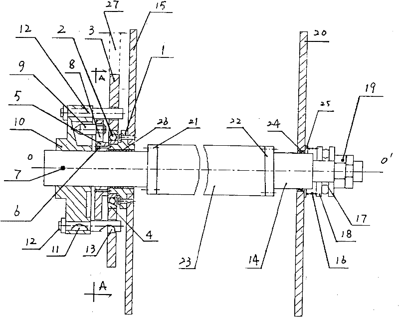
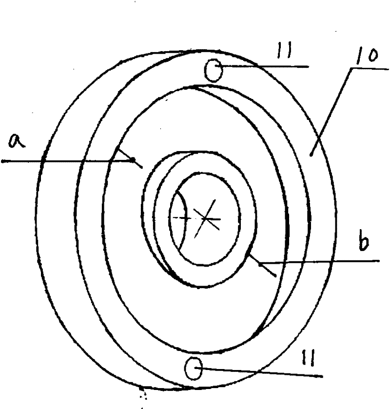
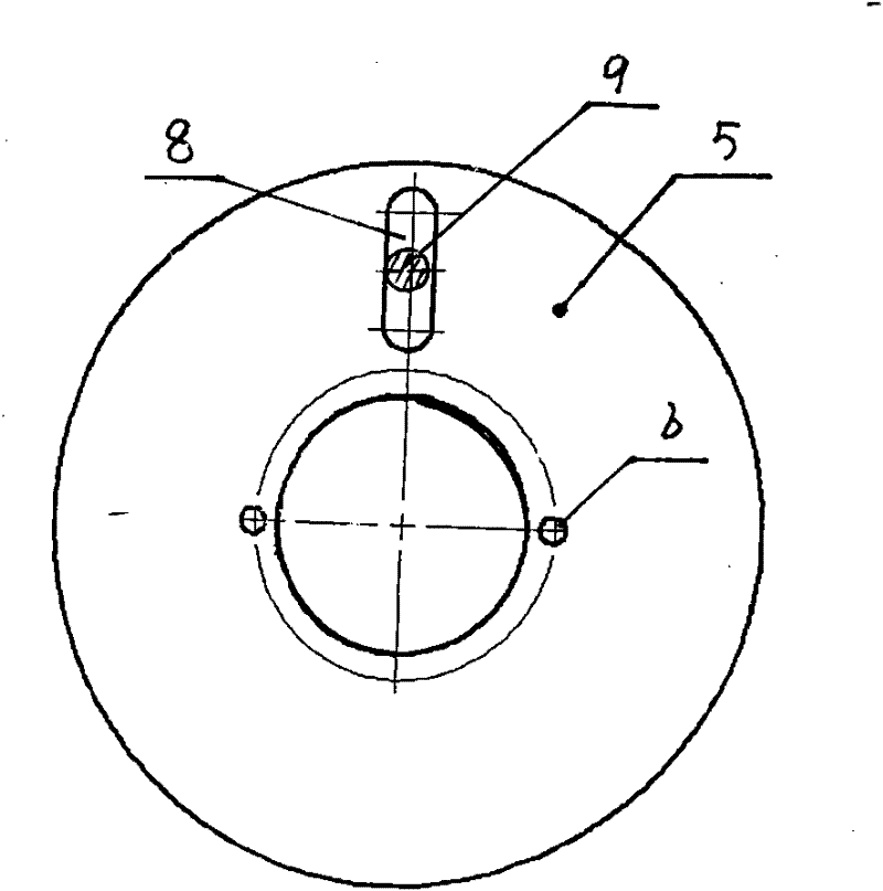
[0014] Such as figure 1 , 2 As shown, the left wall plate 15 is equipped with a bearing seat 1, the inner ring of the bearing 2 is installed on the bearing seat 1, the outer ring of the bearing 2 is installed in the center hole 4 of the inking gear 3, and the matching disc 5 is passed through the screw 6. Installed on the left end surface of the bearing seat 1; the cylindrical cam mechanism is that the left half shaft 7 slides through the left wall plate 15 and at the same time passes through the concentric matching center holes of the bearing seat 1 and the disc 5. The disc 5 has a The radial strip hole 8, in which a position-adjustable push rod 9 is installed, the left end of the push rod 9 is in contact with the contour on the end surface of the cylindrical cam 10, and the cylindrical cam 10 is installed at the end of the left half shaft 7, The cylindrical cam 10 has two symmetrically distributed ...


PUM


Abstract

The invention relates to an oscillating ink device of an offset machine, belonging to the field of printing equipment and solving the problems of endwise slip of a tooth surface and stress deformation of an oscillating ink roll. An oscillating gear (3) is arranged on a bearing block (1) with a disk (5) through a bearing (2), a bearing (1) is fixedly connected with a left wall plate (15), a left half shaft (7) penetrates through the left wall plate (15) and the bearing block (1) in a sliding way, the disk (5) is provided with a driven member ejector rod of a cam mechanism, a column cam (10) isarranged at the end part of the left half shaft (7), and a cylindrical pin (12) on the cam is arranged in a positioning hole (13) of the oscillating gear (3) in a sliding way; and a right half shaft (14) penetrates through a right wall plate (20) in a sliding way and then is provided with a spring (16) and a thrust bearing (17) and then locked by a locking member (19). The invention does not generate tooth surface axial sliding so that the meshing force of the gear acts on the left wall plate, can simultaneously realize circumferential rotation and axial rotation of the oscillating ink roll, can be convenient for regulating the oscillation amount, and has good ink oscillating effect and simple structure.

Description

Technical field [0001] The invention belongs to the field of printing equipment, and relates to an ink stringing device of an offset printing machine. Background technique [0002] The function of the inking device of the offset printing press is to evenly and thin the ink layer through the mutual rolling between the inking roller and the uniforming roller and the simultaneous axial movement of the inking roller. There are basically three schemes in the prior art. One is the crank-rocker mechanism. On one side of the offset press wall (operation surface), the ink chain gear mounted on the ink chain roller shaft is driven to drive the ink chain roller circumference. A crank and rocker mechanism is installed on the other side (transmission surface) of the offset printing press wallboard. The connecting rod drives the ink string roller to move axially through the roller on the pendulum rod. The advantage is that the string momentum is adjustable. The disadvantage is that the struct...

Claims


Application Information

Patent Timeline
Patent Type & Authority Patents(China)
IPC IPC(8): B41F31/00
Inventor 郭俊忠
Owner BEIJING INSTITUTE OF GRAPHIC COMMUNICATION
Why Eureka
Try Eureka