
Multifunctional V-belt fatigue test machine

A fatigue testing machine, multi-functional technology, applied in the direction of applying stable tension/pressure to test the strength of materials, etc., can solve the problems of high failure rate, low test accuracy, low test efficiency, etc., and achieve work stability guarantee and control The effect of improving precision and ensuring test precision

Inactive Publication Date: 2012-03-21
江苏明珠试验机械有限公司
View PDF3 Cites 8 Cited by
  • Summary
  • Abstract
  • Description
  • Claims
  • Application Information

AI Technical Summary

Problems solved by technology

This structure has the following defects: different driving and driven pulleys should be selected for tapes of different cross-section types. Since the pulley is directly connected with the motor shaft and the transmission shaft, it is extremely inconvenient to disassemble and assemble, and frequent disassembly will cause the main shaft to be installed. The error of accuracy leads to the reduction of test accuracy, the application range has certain limitations, and the test efficiency is not high; and the detection system of the existing testing machine does not have the ability to automatically display parameters such as elongation, motor revolutions, and flexion times. Function
The electrical control method also adopts traditional circuit design, which is complex in structure, not conducive to frequent operation, high failure rate, poor stability, low automation level of testing machine, not conducive to operation and feedback of test results

Method used


Image

  • Multifunctional V-belt fatigue test machine
  • Multifunctional V-belt fatigue test machine
  • Multifunctional V-belt fatigue test machine

Examples


Embodiment Construction

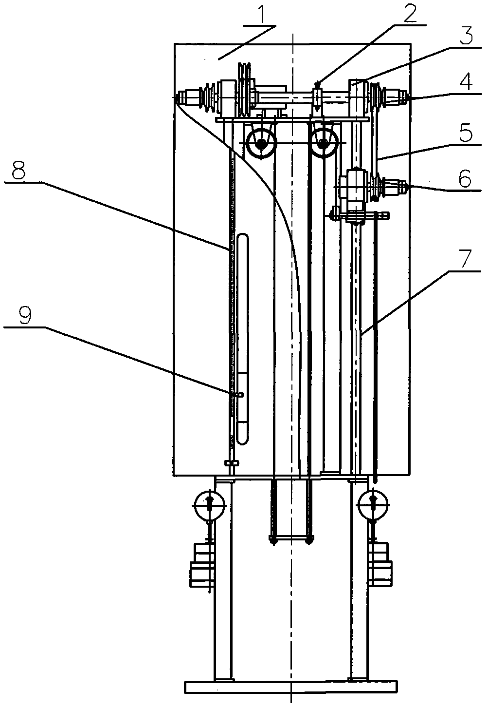
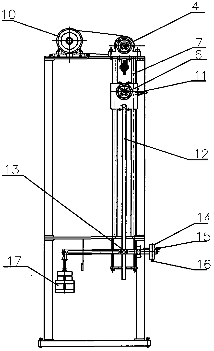
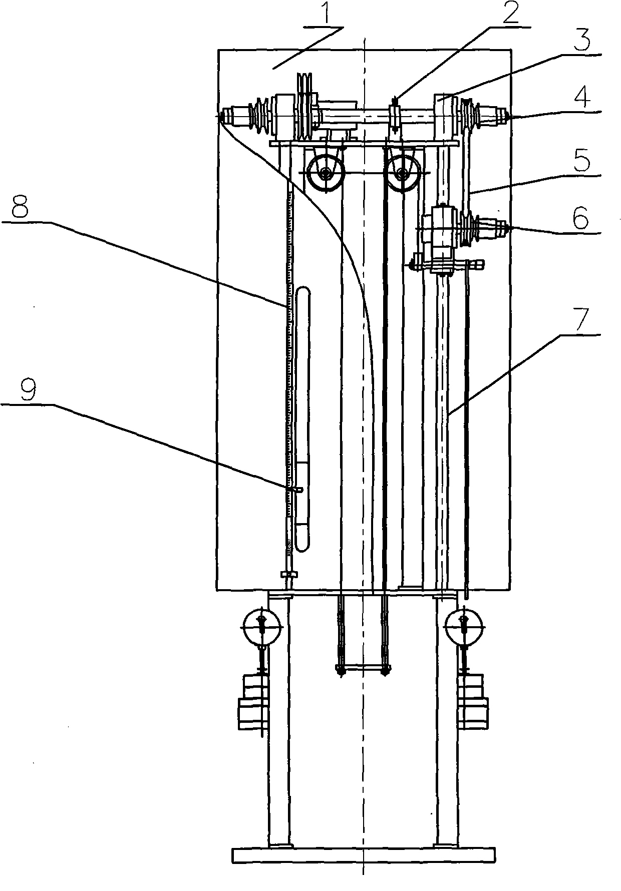
[0010] The invention includes a frame 1, a motor 10 arranged on the frame 1, a testing device and a loading device.

[0011] The test device comprises a driving pulley 4 driven by a motor 10, a driven pulley 6 driven by the driving pulley 4, the driven pulley 4 is arranged on a sliding seat 11, and the sliding seat 11 is arranged along a slide provided on the frame 1. Rail 7 moves up and down, and slide seat 11 lower end connects pull bar 12; The present invention establishes speed control unit 2 on the transmission path of motor 10 and drive pulley 4, and this speed control unit 2 controls drive pulley 4 rotating speeds and can realize no-speed according to the situation. Step speed regulation; a transmission disc 3 is set between the driving pulley 4 and the motor 10 and between the driving pulley 4 and the driven pulley 6. When working, the V-shaped belt 5 is arranged on the driving pulley 4 and the driven pulley 6 On, when the driving pulley 4 and the driven pulley 6 need ...


PUM


Abstract

The invention relates to a multifunctional V-belt fatigue test machine, which comprises a controller and a motor, wherein the motor is arranged on a support frame, the output end of the motor is connected with a test device, the test device comprises a driving belt wheel and a driven belt wheel, the driven belt wheel is arranged on a slide seat capable of upwards and downwards moving, the lower end of the slide seat is connected with a load adding device through a pull rod, and a transmission disc is respectively connected between the motor and the driving belt wheel as well as between the driving belt wheel and the driven belt wheel. The multifunctional V-belt fatigue test machine has the following advantages that: 1, the transmission disc is respectively connected between the motor and the driving belt wheel as well as between the driving belt wheel and the driven belt wheel, so when the belt wheel needs to be replaced according to conditions, the belt wheels do not need to be dismounted from a main shaft, the belt wheels are dismounted from the transmission disc, then, the new belt wheel is connected onto the transmission belt, the mounting and the dismounting are very convenient, and the test precision is ensured; and 2, the multifunctional V-belt fatigue test machine adopts a central processing unit (CPU) for control, the control precision is further improved, and the work stability of the test machine is also greatly ensured.

Description

technical field [0001] The invention relates to a testing machine in the technical field of rubber testing, in particular to a V-belt fatigue testing machine. Background technique [0002] In order to test the fatigue life of ordinary V-belts, washing machine V-belts, V-ribbed belts and other tapes, it is necessary to use a test device to perform a flex test. Invention Patent No. 2005200696175 provides a common V-belt fatigue testing machine, its structure is The tape is installed on the driving and driven pulleys, and the belt is subjected to a running test at a certain speed and pre-tightening force, and the fatigue life of the tape is judged after a specified period of time. This structure has the following defects: different driving and driven pulleys should be selected for tapes of different cross-section types. Since the pulley is directly connected to the motor shaft and the transmission shaft, it is extremely inconvenient to disassemble, and frequent disassembly will...

Claims


Application Information

Patent Timeline
Patent Type & Authority Applications(China)
IPC IPC(8): G01N3/08G01N3/14
Inventor 朱安明
Owner 江苏明珠试验机械有限公司
Learn More