Method for machining involute gear

A technology of involute gears and processing methods, applied to elements with teeth, belts/chains/gears, gear teeth, etc., can solve problems that do not conform to the basic meshing laws, achieve the effect of preventing interference and ensuring transmission accuracy

Inactive Publication Date: 2005-08-31
喻胜
View PDF0 Cites 9 Cited by
  • Summary
  • Abstract
  • Description
  • Claims
  • Application Information

AI Technical Summary

Problems solved by technology

[0003] The purpose of the present invention is to overcome the problem that the tooth top line of the rack cutter reaches the limit meshing point, also known as the theoretical meshing point N, in the existing normal machining method. 1 When it has entered the base garden, what is cut out is not an involute but an ordinary curve, which does not conform to the basic meshing law, and avoids problems in processing ordinary curves in the base garden. The invention provides a processing method for involute gears , the processing method determines the correct feed limit position and the limit meshing point, also known as the theoretical meshing point N B1 point, the top line of the rack knife tooth reaches the limit position of the feed, that is, the limit meshing point is also called the theoretical meshing point N B1 , the minimum number of teeth z of the cut gear min =33.16, when the number of teeth of the gear to be cut is less than 33.16, the rack cutter is processed with positive displacement, displacement xm, minimum displacement coefficient x min =0.0301536(z min -z), which prevents the tooth top line of the rack cutter from entering the base circle and cuts the ordinary curve, which affects the strength of the tooth root, and ensures that the meshing tooth profile of the cut gear is involute, which conforms to the basic meshing law

Method used


Image

  • Method for machining involute gear
  • Method for machining involute gear
  • Method for machining involute gear

Examples


Embodiment Construction

[0013] Below in conjunction with accompanying drawing and embodiment the present invention will be further described:

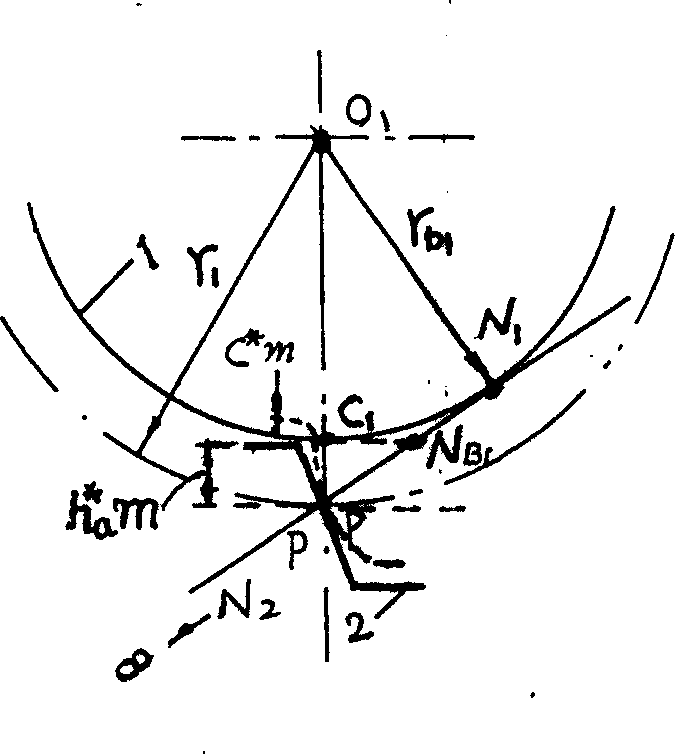
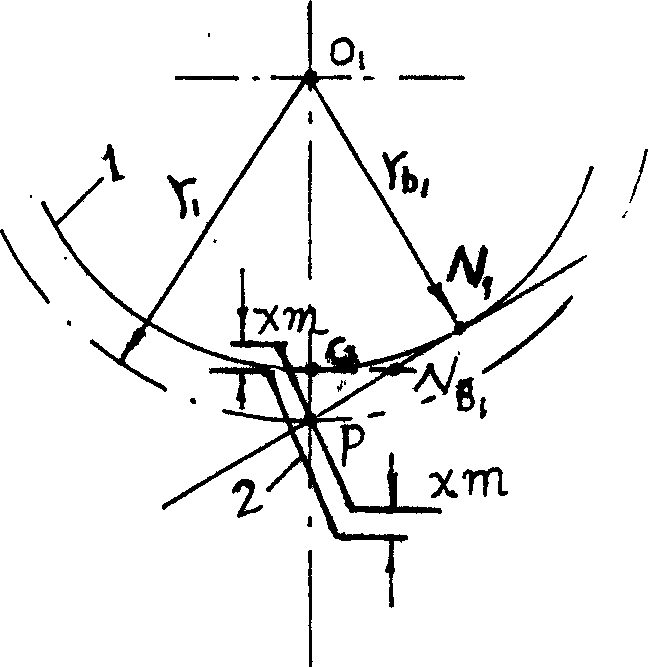
[0014] figure 1 Among them, rack cutter 1 cuts the limit position of gear 2, and the tooth top line of rack cutter is tangent to the base circle of gear C 1 point, and intersects the meshing line at N B1 The point is the limit meshing point of the gear, also known as the theoretical meshing point. In order to prevent the top line of the rack blade from exceeding the limit meshing point, it is also called the theoretical meshing point N B1 , the radius r of the indexing circle of the cut gear 1 and base circle radius r b1 The minimum distance between is the standard addendum height h * a m, national standard addendum height factor h * a =1, the minimum number of teeth can be calculated, h * a m = r 1 2 ...


PUM


Abstract

A technology for machining the involute gear is disclosed. When the tooth top line of standard rack bar tool is tangent with the base circle of gear to be machined, it is an extreme position of advancing tool. When it is said extreme position, the crossing point between said tooth top line and the engaging line is the extreme engaging point. When said tooth top line is advanced to the extreme engaging point, the minimal number of the teeth on the gear is 33.16. When the number of the teeth on the gear is less than 33.16, the rack bar tool moves is the base circle of the gear of machine the involute gear.

Description

Technical field [0001] The invention relates to a processing method of a standard involute cylindrical spur gear Background technique [0002] When the involute standard rack cutter introduced by the existing mechanical principles and mechanical books about gears is used to process the involute standard cylindrical spur gear with the Fan Cheng method, the standard rack cutter is one tooth tip clearance c higher than the standard rack * m, to ensure that the gear transmission has a top clearance c * m, this part of the blade is a circular arc rather than a straight line, which is used to cut the transition curve part of the tooth root of the gear, not the involute line. When discussing the cutting of the gear in the future, the height of the top of the knife will not be taken into account. It is considered that the tooth The height from the indexing line of the bar knife to the tooth top line is h * a m; the tooth top line of the rack cutter cannot exceed the limit meshing...

Claims


Application Information

Patent Timeline
Patent Type & Authority Applications(China)
IPC IPC(8): B23F5/00B23F5/14B23F5/26
Inventor 喻胜
Owner 喻胜
Why Eureka
Try Eureka