
Quick positioning type automatic transmission device

A transmission device and positioning technology, applied in the direction of conveyor, mechanical conveyor, transportation and packaging, etc., can solve the problems of inconsistent speed on both sides of the fixture, large impact force, complex structural design, etc.

Active Publication Date: 2017-01-18
SHENZHEN XING GRAIN AUTOMATION CO LTD
View PDF9 Cites 8 Cited by
  • Summary
  • Abstract
  • Description
  • Claims
  • Application Information

AI Technical Summary

Problems solved by technology

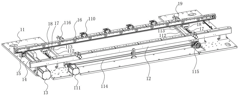
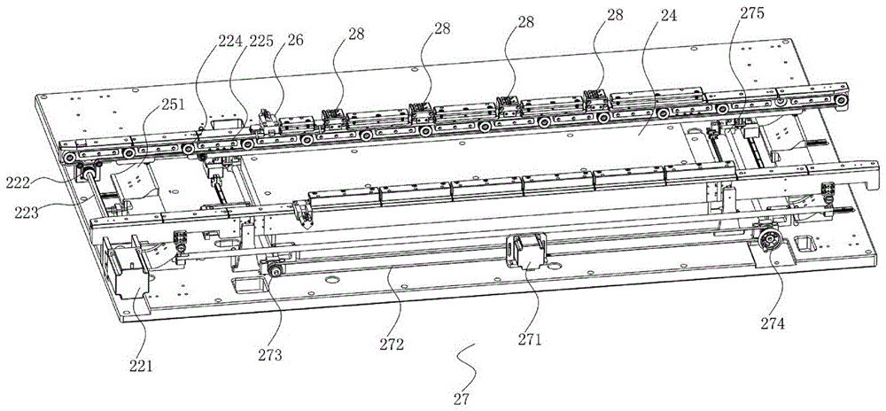
[0004] The above two transmission mechanisms use timing belts set at intervals to transmit the jigs. In the actual work process, affected by the size of the jigs, it is necessary to ensure that the distance between the two timing belts can be adjusted to meet the requirements of various sizes of jigs to the greatest extent. Therefore, it is necessary to add a spacing adjustment mechanism, the structural design is complex, and the manufacturing cost is high; in addition, the transmission structure of double synchronous belts is adopted. In the actual transmission process, due to the transmission accuracy or other factors, the transmission speed of the two synchronous belts may exist. The difference will lead to inconsistent speeds on both sides of the jig conveyed by the two synchronous belts, and the jig will collide with the guide support plate / guide frame, which will affect the normal transmission of the jig
[0005] In addition, after the jig is transferred, it needs to be positioned on the timing belt so that the manipulator can transport the product / parts to be processed on the jig to the processing station. The jig positioning needs to be carried out from the front and rear directions of the jig at the same time. Some jig positioning mechanisms generally use a cylinder-driven stopper to extend into the front of the jig to block positioning. This positioning method is rigid positioning and does not have a buffer function. The impact force during positioning is large, and positioning stability is poor, which affects the treatment. In addition, the existing jig positioning structure adopts an active positioning method, that is, through a power mechanism such as a cylinder, it is actively extended to the moving jig, and the jig is positioned and fixed from the front, back, and top, and the structural design is complicated. Due to the time required for the movement of power mechanisms such as cylinders, it takes a long time for jig positioning. The time used for the positioning of existing jigs is generally more than 5s, which cannot meet the needs of high-speed transmission.

Method used


Image

  • Quick positioning type automatic transmission device
  • Quick positioning type automatic transmission device
  • Quick positioning type automatic transmission device

Examples


Embodiment Construction

[0032] The present invention will be further described below in conjunction with accompanying drawing:

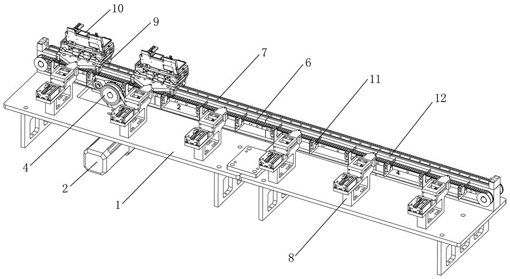
[0033] Such as Figure 3 to Figure 11 As shown, the technical solution adopted by the present invention is as follows: a fast positioning automatic transmission device, including a transmission platform 1, a transmission mechanism, a first synchronous belt 6, a second synchronous belt 7, a transmission seat 9, a jig 10 and a positioning mechanism 8. Wherein, the above-mentioned transmission platform 1 is placed horizontally on the working platform, and a strip-shaped support 12 is provided on the transmission platform 1; the above-mentioned first synchronous belt 6 and the second synchronous belt 7 are respectively arranged on both sides of the support 12, And tensioned by the tensioning pulley fixed on the side wall of the support 12; Seat 12 side synchronous circulation movement; above-mentioned transmission seat 9 comprises at least two, and transmission seat 9 is place...


PUM


Abstract

The invention discloses a quick positioning type automatic transmission device. The quick positioning type automatic transmission device comprises a transmission platform, a transmission mechanism, a first synchronous belt, a second synchronous belt, at least two transmission seats, a jig and at least two positioning mechanisms, wherein a strip-shaped support seat is arranged on the transmission platform; the first synchronous belt and the second synchronous belt are respectively arranged on both sides of the support seat; the transmission mechanism is respectively connected with the first synchronous belt and the second synchronous belt; the at least two transmission seats are arranged on the first synchronous belt and the second synchronous belt and are driven to move forward by the first synchronous belt and the second synchronous belt; the jig is fixedly arranged on the transmission seats; and the at least two positioning mechanisms are arranged beside the support seat at intervals, the positioning mechanisms protrude towards the support seat, and the transmission seats are buckled and connected with the positioning mechanisms when the transmission seats move to the positioning mechanisms, so that the transmission seats are blocked and positioned by virtue of the positioning mechanisms. The quick positioning type automatic transmission device has the advantage of simple design; a single-guide rail guide structure is adopted, so that the transmission precision and stability are effectively increased; passive positioning is adopted, so that the positioning time is effectively shortened.

Description

technical field [0001] The invention relates to the field of automatic machinery, in particular to a fast positioning automatic transmission device. Background technique [0002] In the field of automatic processing and manufacturing, the automatic transportation and transmission of materials is an essential process. The efficiency of automatic transportation and transmission of materials directly affects the production capacity of the entire automation device; in the existing automatic material transmission process, various The shape and size of the material are different, so in the actual transmission process, it is generally necessary to use a fixing mechanism. The common fixing mechanism is a jig, which clamps and fixes the material or product through the jig, and then controls the movement of the jig to realize the material or product. transmission. [0003] Traditional jig transport mechanisms generally use synchronous belts as power drive components; figure 1 As sho...

Claims


Application Information

Patent Timeline
Patent Type & Authority Applications(China)
IPC IPC(8): B65G35/00
CPCB65G35/00
Inventor 劳世敏
Owner SHENZHEN XING GRAIN AUTOMATION CO LTD
Learn More