Method for anchoring fiber sheet by using parallel double rods
A fiber sheet and parallel rod technology, which is applied in the processing of building materials, building maintenance, structural elements, etc., can solve the problems of the size of the body, the difficulty of operation, and the anchoring effect is not ideal, so as to improve the utilization efficiency and the scope of application. , Easy to operate, reliable effect
- Summary
- Abstract
- Description
- Claims
- Application Information
AI Technical Summary
Problems solved by technology
Method used
Image
Examples
Embodiment 1
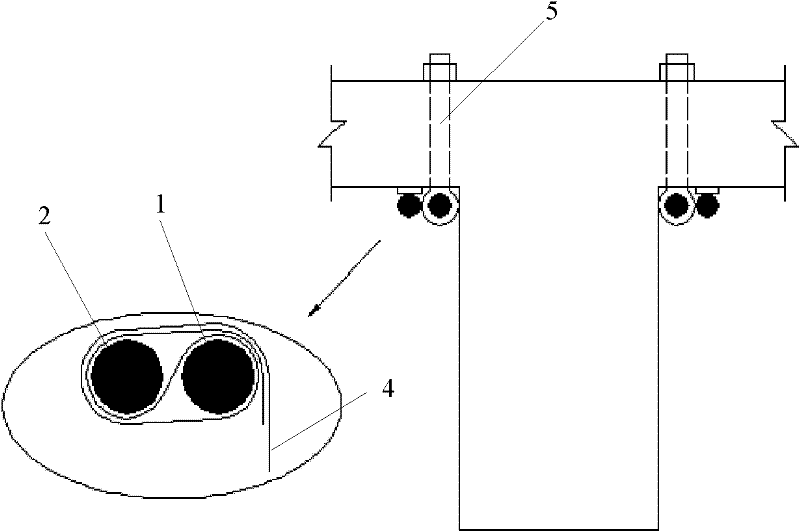
[0034] Use jointed rods with holes to assist anchoring: such as image 3 As shown, the shear reinforcement of the T-section beam is carried out, assuming that 5 fiber sheets are used, the U-shape is attached to the bottom surface of the section and the 2 sides are turned and extended to the bottom of the flange plate. On the left side of the beam section, one of the 2 rods (the rods can be steel bars) is inserted into the holes of the 6 (=5+1) joint-shaped rods with holes before winding the fiber strip, and the adjacent 2 rods are The clear distance between the jointed rods with holes is not less than the width of the fiber strip ( image 3 The hinged rod with holes on the left side of the middle beam section looks like 1, but from the side of the beam, there are 6); Next to the rod, the hole wall of the joint-shaped rod with holes keeps the two rods parallel and leaves a gap; after the end of the fiber strip is self-locked around the parallel rod, the six joint-shaped rods w...
Embodiment 2
[0037] like Figure 4 and Figure 5 shown, using Figure 5 Flexible sheet material parallel rod anchoring device with anchor holes shown, Figure 5 The 2 round rods in the Figure 4 2 round rods in . After the end of the strip-shaped flexible sheet is wrapped around the parallel double rods in the parallel-rod anchoring device of the flexible sheet-shaped material, the auxiliary anchor is used to pass through the anchoring hole in the parallel-rod anchoring device of the flexible sheet-shaped material, and then inserted Anchoring in previously prepared holes on external objects.
Embodiment 3
[0039] Anchoring using a flexible sheet material parallel rod anchoring device with a protruding part: a flexible sheet material parallel rod anchoring device with a protruding part is used, and the end of the flexible sheet material is wrapped around the flexible sheet material parallel rod anchoring After the parallel double rods in the device are self-locked, the protruding part is inserted into the hole of the hinged rod with holes, and then the hinged rod with holes is inserted into the holes prepared in advance on the external object for anchoring.
[0040] Image 6 It is a flexible sheet material parallel rod anchoring device with a protruding part, and the two round rods in the figure are parallel rods.
PUM
 Abstract
Description
Claims
Application Information
 - R&D
- Intellectual Property
- Life Sciences
- Materials
- Tech Scout
- Unparalleled Data Quality
- Higher Quality Content
- 60% Fewer Hallucinations
Browse by: Latest US Patents, China's latest patents, Technical Efficacy Thesaurus, Application Domain, Technology Topic, Popular Technical Reports.
© 2025 PatSnap. All rights reserved.Legal|Privacy policy|Modern Slavery Act Transparency Statement|Sitemap|About US| Contact US: help@patsnap.com


