Internal heat exchanger assembly

一种内部热交换器、组件的技术,应用在热交换设备、过热器、制冷组件等方向,能够解决空间有限、困难等问题

Inactive Publication Date: 2010-12-29
MAHLE INT GMBH
View PDF1 Cites 14 Cited by
  • Summary
  • Abstract
  • Description
  • Claims
  • Application Information

AI Technical Summary

Problems solved by technology

Installing this heat exchanger in the engine compartment is difficult due to the limited space inside the engine compartment

Method used


Image

  • Internal heat exchanger assembly
  • Internal heat exchanger assembly
  • Internal heat exchanger assembly

Examples


Embodiment Construction

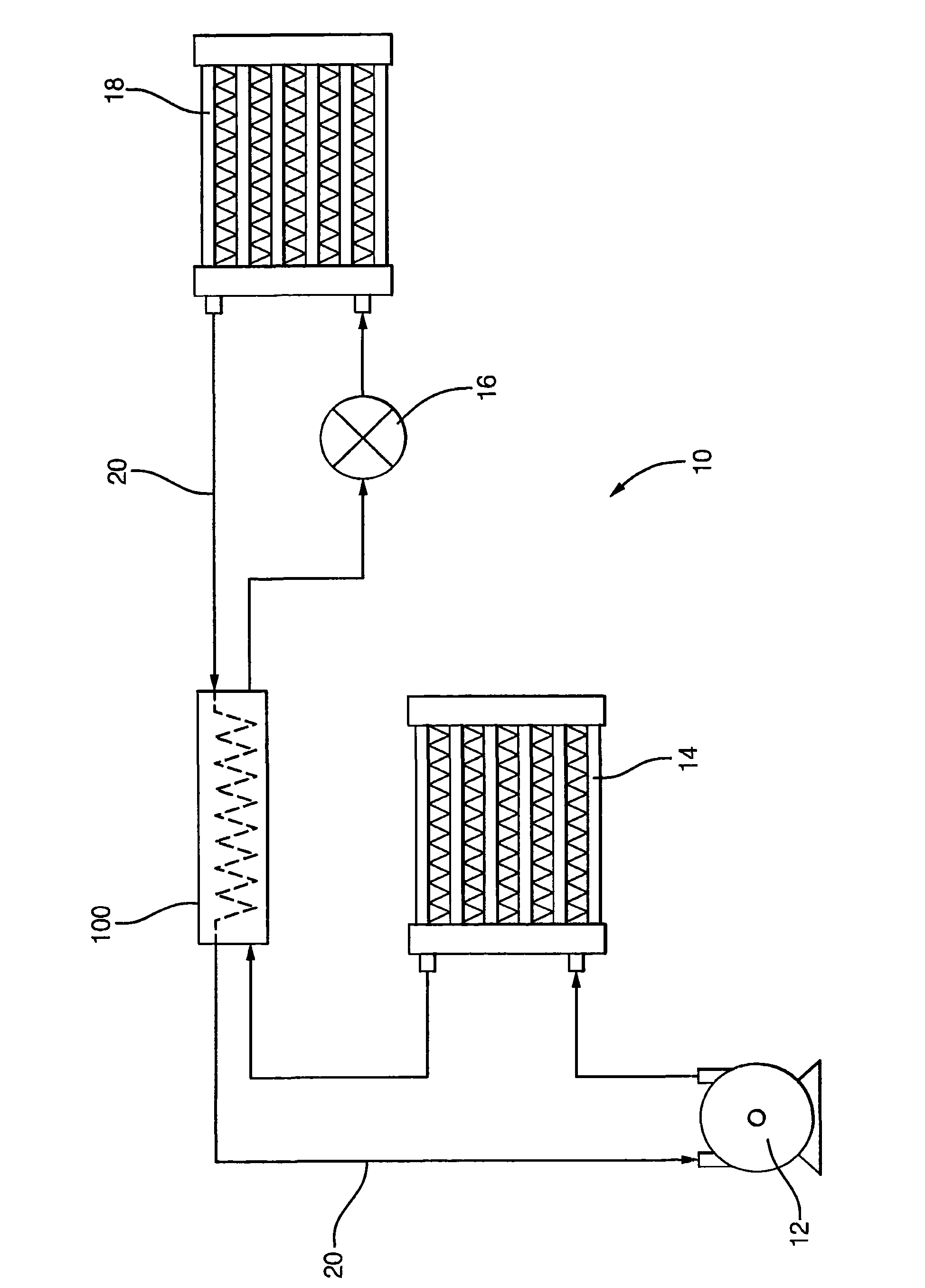
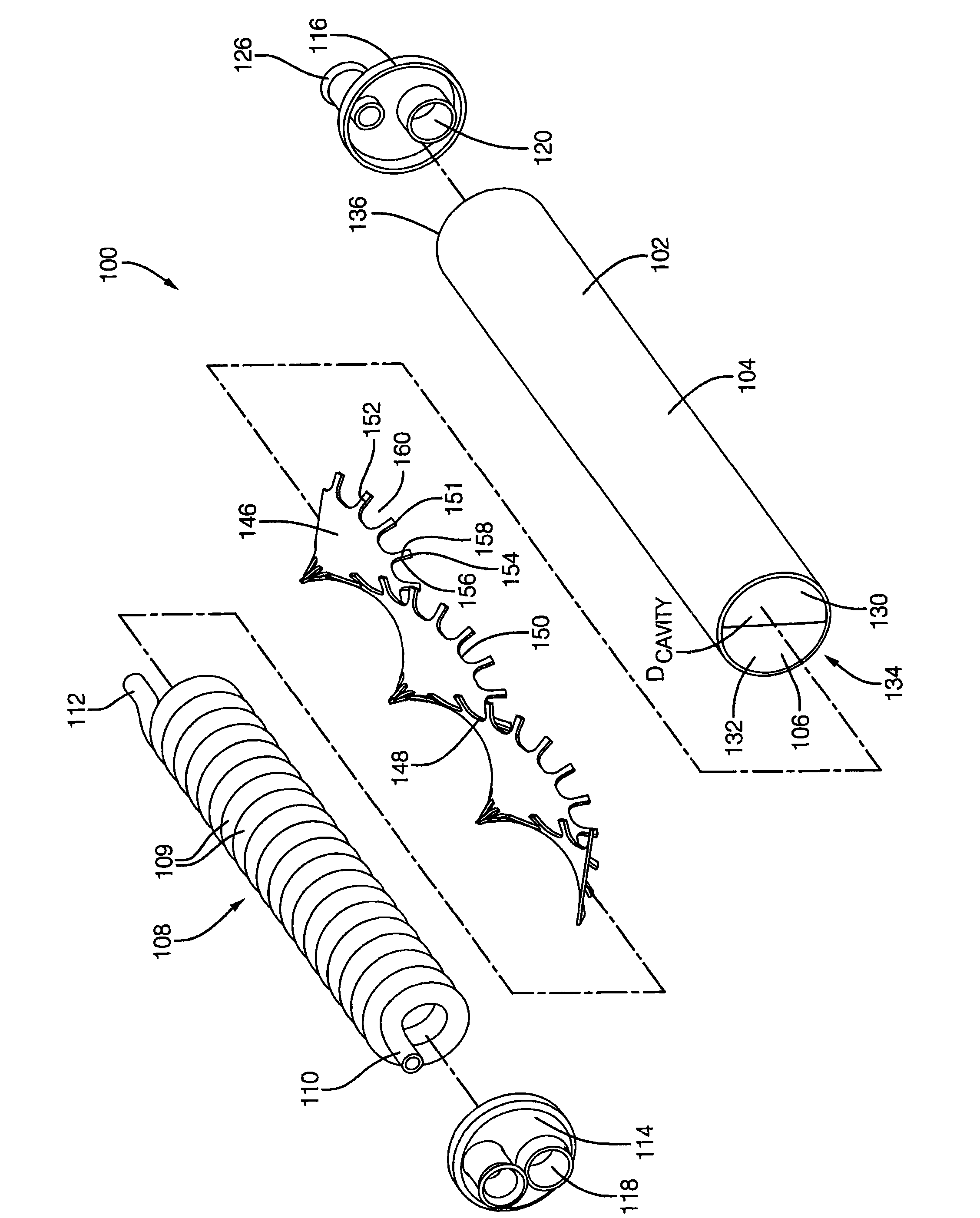
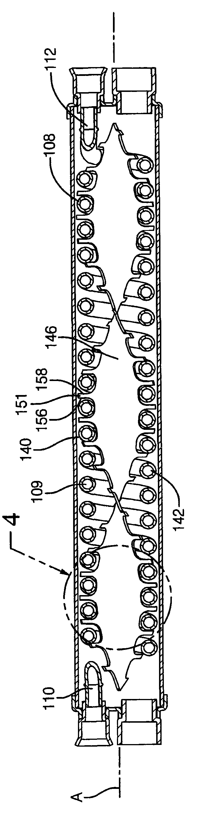
[0020] According to a preferred embodiment of the present invention, refer to Figure 1-4 , the air conditioning system 10 has a compressor 12, a condenser 14, an expansion device 16, an evaporator 18, and a refrigerant pipe 20 hydraulically connecting the above components in series. The air conditioning system 10 further includes an internal heat exchanger 100 to increase the heat transfer capability of the air conditioning system 10 .

[0021] Such as figure 1 As shown in , the low-pressure vapor refrigerant discharged from the evaporator 18 is sucked by the compressor 12 and compressed into a high-pressure vapor refrigerant, which is then discharged to the condenser 14 . In the condenser 14, the high-pressure vapor refrigerant condenses into high-pressure liquid refrigerant. The high pressure liquid refrigerant then passes through an expansion device 16 that regulates refrigerant flow to an evaporator 18 where it expands to a low pressure vapor refrigerant as it absorbs h...


PUM


Abstract

The invention relates to an internal heat exchanger assembly for an air conditioning system, having a housing defining a cylindrical with opposing ends. The ends are sealed with end caps having inlets / outlets. A helical coil tube is coaxially disposed within the cylindrical cavity, in which the helical coil includes two tube ends extending in opposing directions and exiting the cylindrical cavitythrough tube ports provided in the end caps. A twisted elongated strip is coaxially disposed within the cylindrical cavity extending from the first end to the second end. The twisted elongated strip includes a plurality of radially extending fingers adapted to engage the helical coil to maintain the helical coil in a predetermined position.

Description

technical field [0001] The present invention relates to an interior heat exchanger assembly for an automotive air conditioning system; more particularly, to an interior heat exchanger assembly having an interior helical coil held in a predetermined position by an interior baffle , the inner baffle has radially extending fingers defining a double helix. Background technique [0002] A typical automotive air conditioning system includes a compressor, condenser, expansion device, and evaporator. Connecting the above components hydraulically in series are refrigerant tubes capable of carrying high and low pressure refrigerant flow. The two-phase refrigerants used in modern automotive air conditioning systems are an environmentally friendly refrigerant known as R-134a and a low global warming potential (GWP) refrigerant such as HFO-1234yf. [0003] The compressor is often referred to as the heart of the air conditioning system, where the compressor is responsible for compressin...

Claims


Application Information

Patent Timeline
Patent Type & Authority Applications(China)
IPC IPC(8): F25B40/06F28F9/00
CPCF25B40/00F28F9/0132F28D7/024F28F13/06F28D7/106F28D7/022F25B2500/01F28D7/02F28D7/10
Inventor E·沃尔夫四世P·S·凯德尔C·M·科夫斯基J·A·布赖特
Owner MAHLE INT GMBH
Why Eureka
Try Eureka