Thermal contact resistance testing method and equipment

A technology of contact thermal resistance and testing method, which is applied in the field of testing and can solve problems such as large errors, impractical engineering, and many parameters

Inactive Publication Date: 2010-12-29
BEIHANG UNIV
View PDF2 Cites 34 Cited by
  • Summary
  • Abstract
  • Description
  • Claims
  • Application Information

AI Technical Summary

Problems solved by technology

However, these methods have many parameters and large errors, which are not practical in engineering

Method used


Image

  • Thermal contact resistance testing method and equipment
  • Thermal contact resistance testing method and equipment
  • Thermal contact resistance testing method and equipment

Examples


Embodiment Construction

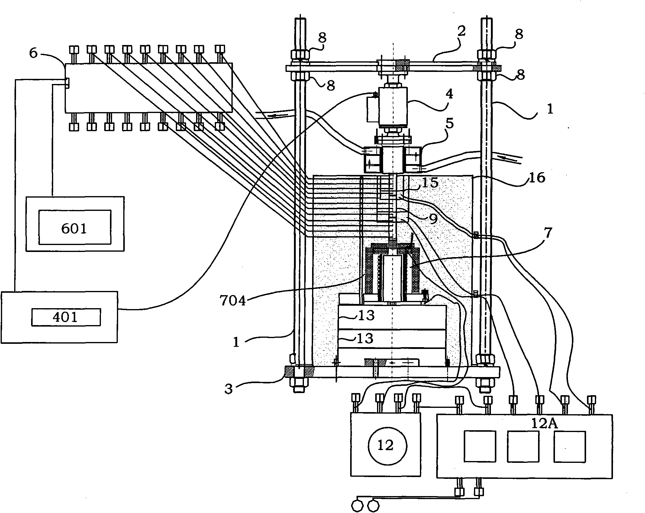
[0049] The present invention will be described in detail below in conjunction with the accompanying drawings and embodiments.

[0050] The invention provides a method for testing thermal contact resistance. The testing method utilizes the characteristics of temperature change of heat flow transmitted between different material interfaces to detect thermal contact resistance of the interface. Therefore, this method is relatively simple, reliable, and has high measurement accuracy and is easy to use. Operational test equipment will do. However, due to the need for sufficient heat exchange between the temperature measuring element and the surrounding medium, it takes a certain amount of time to achieve thermal equilibrium, so the data after reaching a steady state is credible. Based on the above factors, the contact thermal resistance testing method provided by the present invention is specifically realized through the following steps:

[0051] The first step is the preparation ...


PUM


Abstract

The invention discloses a thermal contact resistance testing method belonging to the technical field of tests and comprising the steps of: preparing for test samples and equipment, heating the samples and acquiring the temperatures of test points of the samples, calculating the average temperature of the adjacent samples in the contact interface, and carrying out temperature compensation on the contact interface of the samples; and calculating contact conductance and thermal contact resistance according to the temperature drop of the contact interface of the adjacent samples and the axial heat flow of the samples. According to the requirement of the tests, the heating temperature of a heating device or loading stress of a stress loading device can be regulated, and the thermal contact resistances under different temperatures and stress conditions are tested. The testing method can be used for testing the thermal contact resistances of the test samples under different temperatures and stress conditions, and is easy and simple in implementation.

Description

technical field [0001] The invention belongs to the technical field of testing, and specifically relates to a method and equipment for testing thermal contact resistance, which is suitable for testing thermal contact resistance in different temperature and loading stress ranges, and especially capable of testing thermal contact resistance under high temperature and high contact stress conditions condition. Background technique [0002] When the surfaces of two objects come into contact with each other, no matter how smooth the surfaces are, there are always microscopic incomplete contact points. The contact surface of an object is composed of scattered small contact points, which are separated by large gaps, which may be vacuum or filled with heat transfer medium. Therefore, in addition to the inherent thermal resistance at the contact surface, there is an additional heat transfer resistance - contact thermal resistance. Contact resistance is an important parameter in many...

Claims


Application Information

Patent Timeline
Patent Type & Authority Applications(China)
IPC IPC(8): G01N25/20
Inventor 侯卫国张卫方王宗仁崔本仓唐庆云刘肖丁美丽王晓亮姚婧
Owner BEIHANG UNIV
Why Eureka
Try Eureka