Permanent magnet coupling device for cylindrical transmission shaft

A technology of permanent magnet coupling and transmission shaft, applied in the field of load speed regulation system and motor driving, it can solve the problems of low heat dissipation efficiency, insufficient processing, and too large power capacity.

Inactive Publication Date: 2010-12-29
北京麦格纳传动科技有限公司
View PDF1 Cites 63 Cited by
  • Summary
  • Abstract
  • Description
  • Claims
  • Application Information

AI Technical Summary

Problems solved by technology

③The heat dissipation technology adopted is relatively backward. The currently known permanent magnetic coupling drive or speed regulation technology of the transmission shaft and its products mainly use traditional blade-type radiators and water cooling systems for heat dissipation. Not only the heat dissipation efficiency is not high, but due to the structure Limitation, there are many heat-dissipating components that cannot be dealt with or dealt with in place, so the power capacity per unit volume of the product cannot be too large

Method used


Image

  • Permanent magnet coupling device for cylindrical transmission shaft
  • Permanent magnet coupling device for cylindrical transmission shaft
  • Permanent magnet coupling device for cylindrical transmission shaft

Examples


Embodiment 1

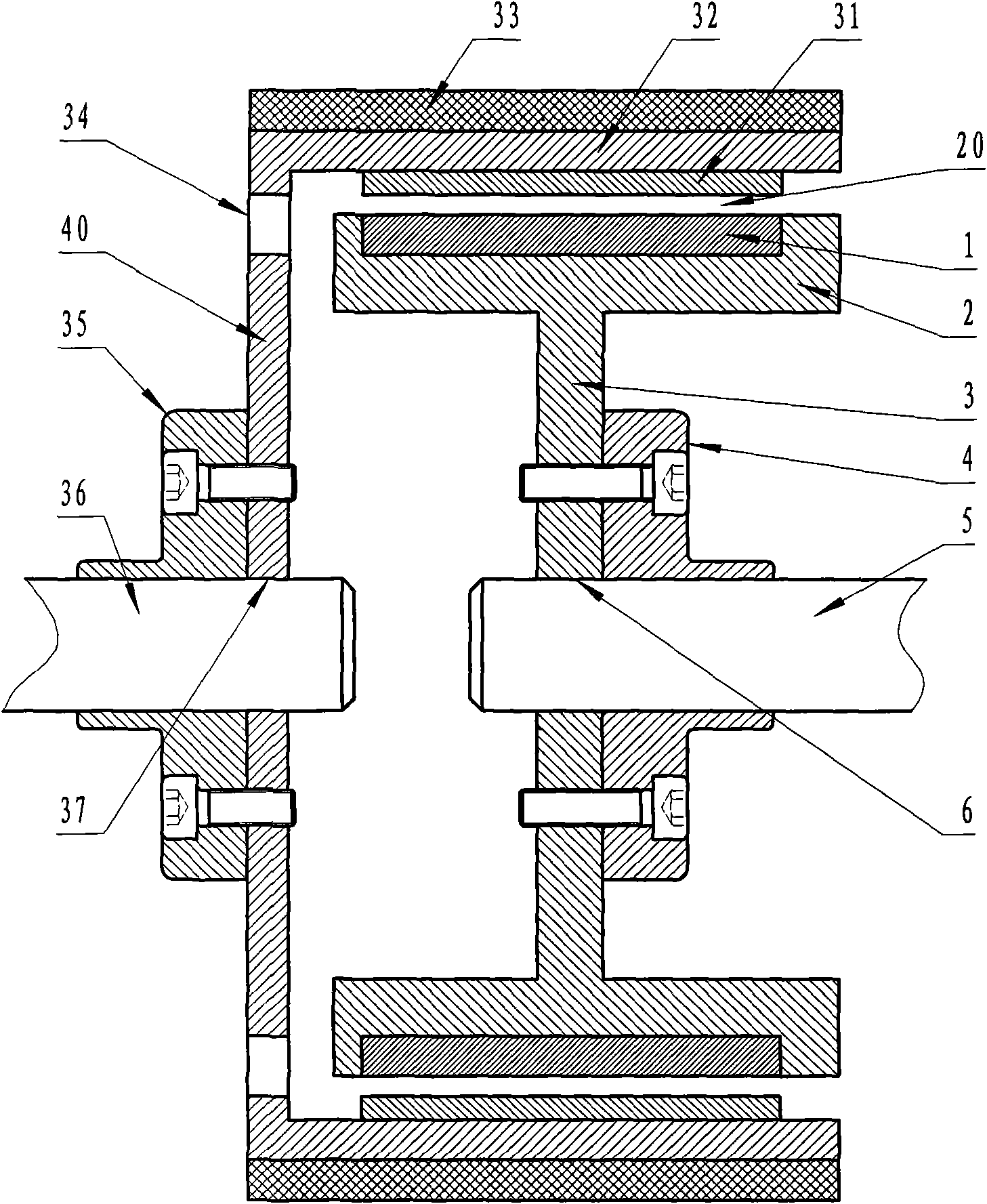
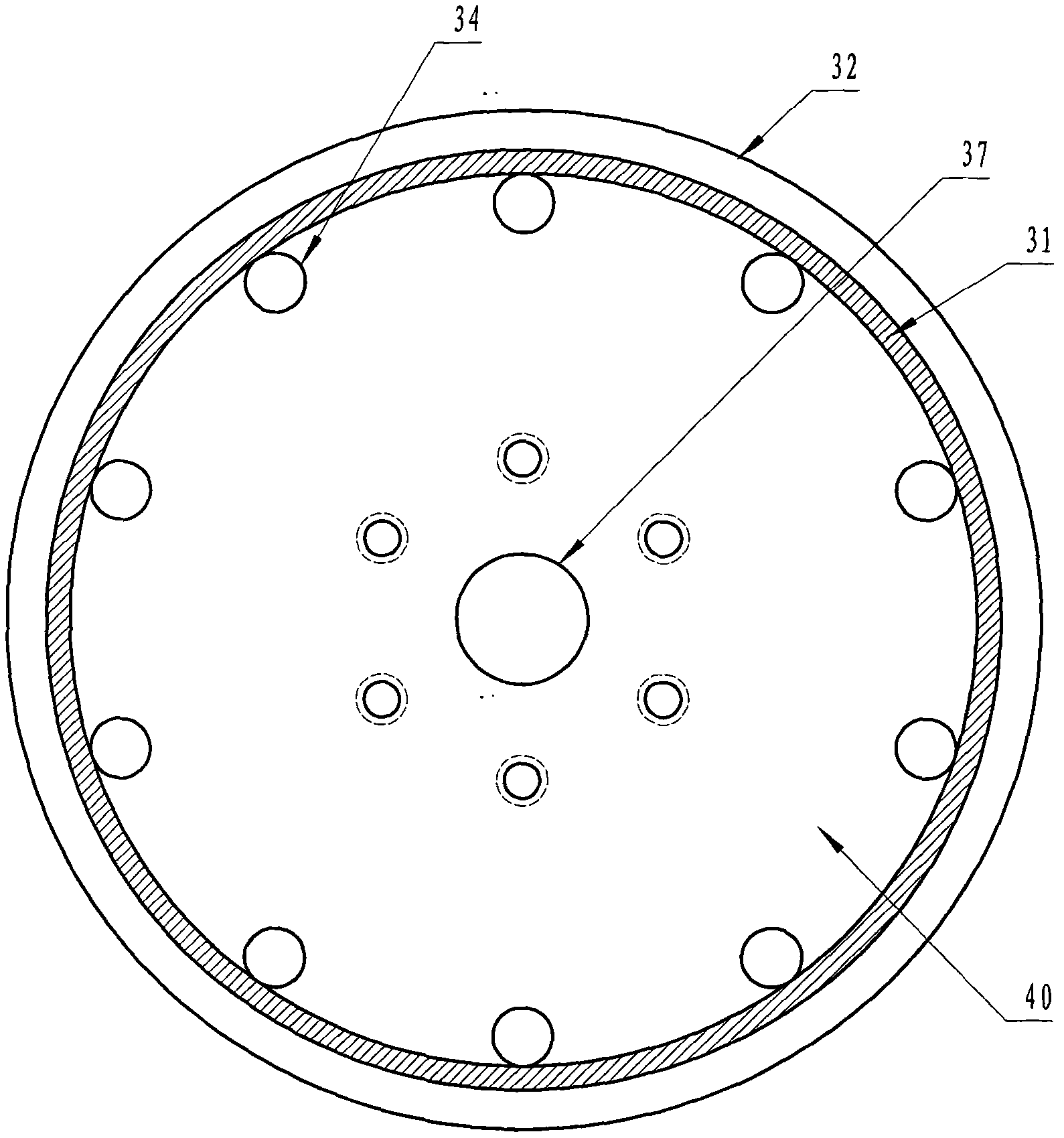
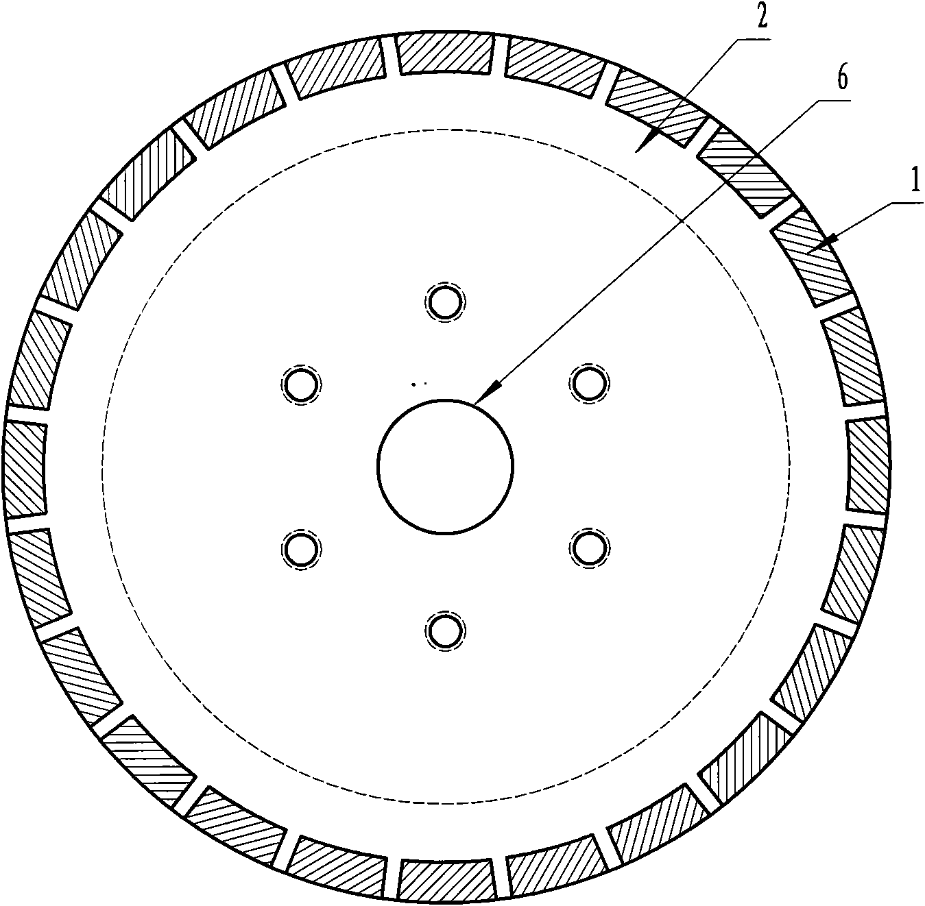
[0062] Such as figure 1 , figure 2 , image 3 and Figure 4As shown, it consists of a group of two cylindrical outer rotor cylinders (31, 32 and 33) and inner rotor cylinders (1 and 2) coupled with radial permanent air gap magnetic fields (20) nested in each other. Components, a pair of outer rotor cylinder shaft coupling mechanisms (32, 40) in a cylindrical direct connection structure composed of the outer rotor cylinder wall (32), the outer rotor cylinder end wall (40) and the shaft hole (37) provided thereon and 37), a pair of inner rotor barrel coupling mechanism (2, 3 and 6), and the corresponding input coupling (35) and output coupling (4); wherein the inner side of the outer rotor cylinder wall (32) serves as the radial magnetic field of the radial magnetic field conductor cylinder (31) The conductor mounting plate (32) is used, and a section of cylindrical radial magnetic field conductor cylinder (31) is fixedly attached to the inner side of the radial magnetic fi...

Embodiment 2

[0066] Such as Figure 5 , Figure 6 , Figure 7 , Figure 8 and Figure 9 As shown, it consists of a set of two cylindrical outer rotor cylinders (131 and 132) and inner rotor cylinders (101 and 102) coupled with radial permanent air gap magnetic fields (120) nested in each other, a pair of The outer rotor cylinder coupling mechanism (132, 140 and 137) of the cylindrical direct connection structure composed of the outer rotor cylinder wall (132), the outer rotor cylinder end wall (140) and the shaft hole (137) provided thereon, A pair of inner rotor barrel coupling mechanisms (102, 103 and 106) with a direct connection structure consisting of the inner rotor barrel wall (102), the inner rotor barrel end wall (103) and the shaft hole (106) provided thereon, and the corresponding input coupling (135) and output coupling (104); wherein the inner side of the outer rotor cylinder wall (132) serves as the radial magnetic field of two radial magnetic field squirrel-cage armature...

Embodiment 3

[0069] Such as Figure 10 , Figure 11 , Figure 12 , Figure 13 and Figure 14As shown, it consists of a group of two cylindrical mutually nested radial permanent air gap magnetic fields (220) and an outer rotor cylinder (231 and 232, 218 and 218) coupled with an axial permanent air gap magnetic field (221) 232, 239 and 240, 233) and inner rotor barrel (201 and 202, 212 and 202, 213 and 217) assembly, a pair of outer rotor barrel wall (232) and outer rotor barrel end wall (240) and its upper The outer rotor cylinder shaft coupling mechanism (232, 240 and 237) of the cylindrical direct coupling structure composed of the provided shaft hole (237), a pair of inner rotor cylinder wall (202) and inner rotor cylinder end wall (203 and 208 ) and the inner rotor tube coupling mechanism (202, 203 and 206, 202, 208 and 207, 250) composed of the shaft holes (206 and 207) and the non-circular central short shaft (251), respectively, and the corresponding The input coupling (235) and...


PUM


Abstract

A permanent magnet coupling device for a cylindrical transmission shaft comprises at least a group of outer rotor drum assemblies and a group of inner rotor drum assemblies, at least a pair of outer rotor drum shaft coupling mechanisms adaptive to the outer rotor drums, at least a pair of inner rotor drum shaft coupling mechanisms adaptive to the inner rotor drums and corresponding input shaft couplings and output shaft couplings, wherein each group of outer rotor drum assemblies and each group of inner rotor drum assemblies are nested with each other and coupled by permanent magnet air gap magnetic fields; at least radial air gap magnetic field permanent magnet coupling assemblies or axial air gap magnetic field permanent magnet coupling assemblies are arranged and assembled on the adjacent corresponding positions of the outer rotor drums and the inner rotor drums; and the outer rotor drums and the inner rotor drums are coupled with the corresponding input shaft couplings or output shaft couplings by the corresponding adaptive rotor drum coupling mechanisms. The device has the characteristics of higher transmission efficiency, simple and reliable structure, convenient installation, resistance to severe environment, tolerance for shaft eccentricity, load isolation, reduction of vibration and noises, prolonging of equipment life, etc, and has the advantages of not damaging the motors and not affecting the safety of power grids.

Description

technical field [0001] The invention relates to the field of motor drive and load speed regulation systems, in particular to a permanent magnetic coupling device for a cylindrical transmission shaft. Background technique [0002] At present, energy saving and consumption reduction has become the focus of the whole society and the goal of scientific development. The electricity consumption of the motor system accounts for about 60% of the global electricity consumption, of which the electricity consumption of fans, pumps, compressors and air-conditioning refrigerators account for 10.4%, 20.9%, 9.4% and 6% of the global electricity consumption respectively. The motor system has a large quantity and a wide range, and the potential for power saving is huge. From a domestic point of view, the total installed capacity of various existing motor systems is about 420 million kilowatts, and the operating efficiency is 10-20 percentage points lower than the advanced level abroad, whic...

Claims


Application Information

Patent Timeline
Patent Type & Authority Applications(China)
IPC IPC(8): H02K49/10
CPCH02K49/106
Inventor 余亚莉林贵生
Owner 北京麦格纳传动科技有限公司
Why Eureka
Try Eureka