Drive circuit of light-emitting diode and illumination device

A technology of light emitting diodes and driving circuits, which is applied to lighting devices, lighting device components, circuit layouts, etc., can solve the problems of increasing production costs, high unit price of driving chips, and increasing the complexity of peripheral circuits, and achieves the effect of avoiding flickering.

Inactive Publication Date: 2010-12-29
CAL COMP ELECTRONICS
View PDF3 Cites 6 Cited by
  • Summary
  • Abstract
  • Description
  • Claims
  • Application Information

AI Technical Summary

Problems solved by technology

However, the above-mentioned technology will increase the complexity of peripheral circuits, and will also increase the production cost due to the high unit price of the driver IC.

Method used


Image

  • Drive circuit of light-emitting diode and illumination device
  • Drive circuit of light-emitting diode and illumination device
  • Drive circuit of light-emitting diode and illumination device

Examples


Embodiment Construction

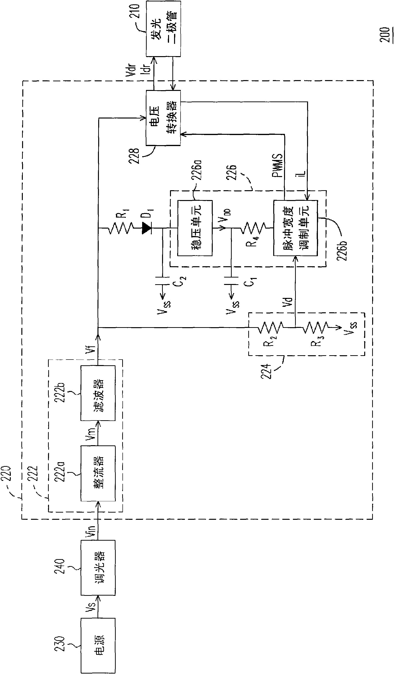
[0075] figure 2 A lighting device according to an embodiment of the present invention is shown. Please refer to figure 2 , the lighting device 200 includes a light emitting diode (light emitting diode, LED) 210 and a driving circuit 220 . The drive circuit 220 includes a rectification unit 222, a voltage divider circuit 224, a control unit 226, a voltage converter 228, a resistor R 1 , capacitance C 2 and the diode D 1 . In this embodiment, the lighting device 200 may further include a power supply 230 and a dimmer 240 , wherein the dimmer 240 receives the input voltage Vs provided by the power supply 230 and outputs the AC power Vin according to the conduction condition. In this embodiment, the dimmer 240 may use a tri-electrode AC switch (TRIAC) to implement its function, but is not limited thereto. In addition, TRIAC dimmers can be divided into nine grades of maximum (MAX), first to seventh and minimum (MIN) in order to adjust the illuminance value of the light sour...


PUM


Abstract

The invention discloses a drive circuit of a light-emitting diode and an illumination device. The drive circuit comprises a rectifying unit, a voltage division circuit, a control unit, a voltage converter, a resistor and a capacitor, wherein the rectifying unit rectifies an AC power supply to output a first working voltage; the voltage division circuit receives the first working voltage to generate a voltage division signal; the control unit comprises a voltage-stabilizing unit and a pulse width modulation (PWM) unit, wherein the output end of the voltage-stabilizing unit is coupled with the PWM unit, and the PWM unit outputs a PWM signal; the voltage converter regulates driving voltages and driving currents of the light-emitting diode according to the PWM signal; the resistor is coupled between the output end p of the rectifying unit and the diode; the capacitor is coupled between the power input end of the voltage-stabilizing unit and the grounding end; and the PWM unit regulates the PWM signal according to the voltage division signal and a feedback signal output by the voltage converter.

Description

technical field [0001] The present invention relates to a driving circuit and a lighting device, and in particular to a driving circuit for driving a light emitting diode (LED) and a lighting device using the driving circuit. Background technique [0002] In the related art part of the lighting device, there is usually a dimmer, which is used to control the power supply so that the lighting of the lighting device (such as a light bulb) can not only be turned on and off, but also have the effect of fine-tuning the lighting. figure 1 A known lighting device is shown. Please refer to figure 1 , the lighting device 100 has a power source 102 , a dimmer 104 and a light bulb 106 . The power supply 102 provides an input voltage, wherein the input voltage can be AC. When the user controls the luminous effect of the light bulb 106 through the dimmer 104 , the dimmer 104 will provide a voltage according to the conduction condition to fine-tune the luminous effect of the light bulb ...

Claims


Application Information

Patent Timeline
Patent Type & Authority Applications(China)
IPC IPC(8): H05B37/00H05B37/02F21V23/00F21Y101/02
Inventor 王俊雄陈志宗王濠源刘耀声何况
Owner CAL COMP ELECTRONICS
Why Eureka
Try Eureka