Bearing device and rotary machine

A bearing device and bearing box technology, applied in the field of rotating machinery, can solve problems such as insufficient following, and achieve the effect of preventing wear

Inactive Publication Date: 2010-12-29
MITSUBISHI HEAVY INDUSTIES COMPRESSOR CORP
View PDF2 Cites 19 Cited by
  • Summary
  • Abstract
  • Description
  • Claims
  • Application Information

AI Technical Summary

Problems solved by technology

In this slanted pad bearing, the back surface on the opposite side to the side in contact with the rotation shaft of the pad is curved outward. With such a curved shape, it follows the deformation of the rotation shaft. Insufficient follow-up, there is a problem in stabilizing the bearing characteristics

Method used


Image

  • Bearing device and rotary machine
  • Bearing device and rotary machine
  • Bearing device and rotary machine

Examples


no. 1 approach

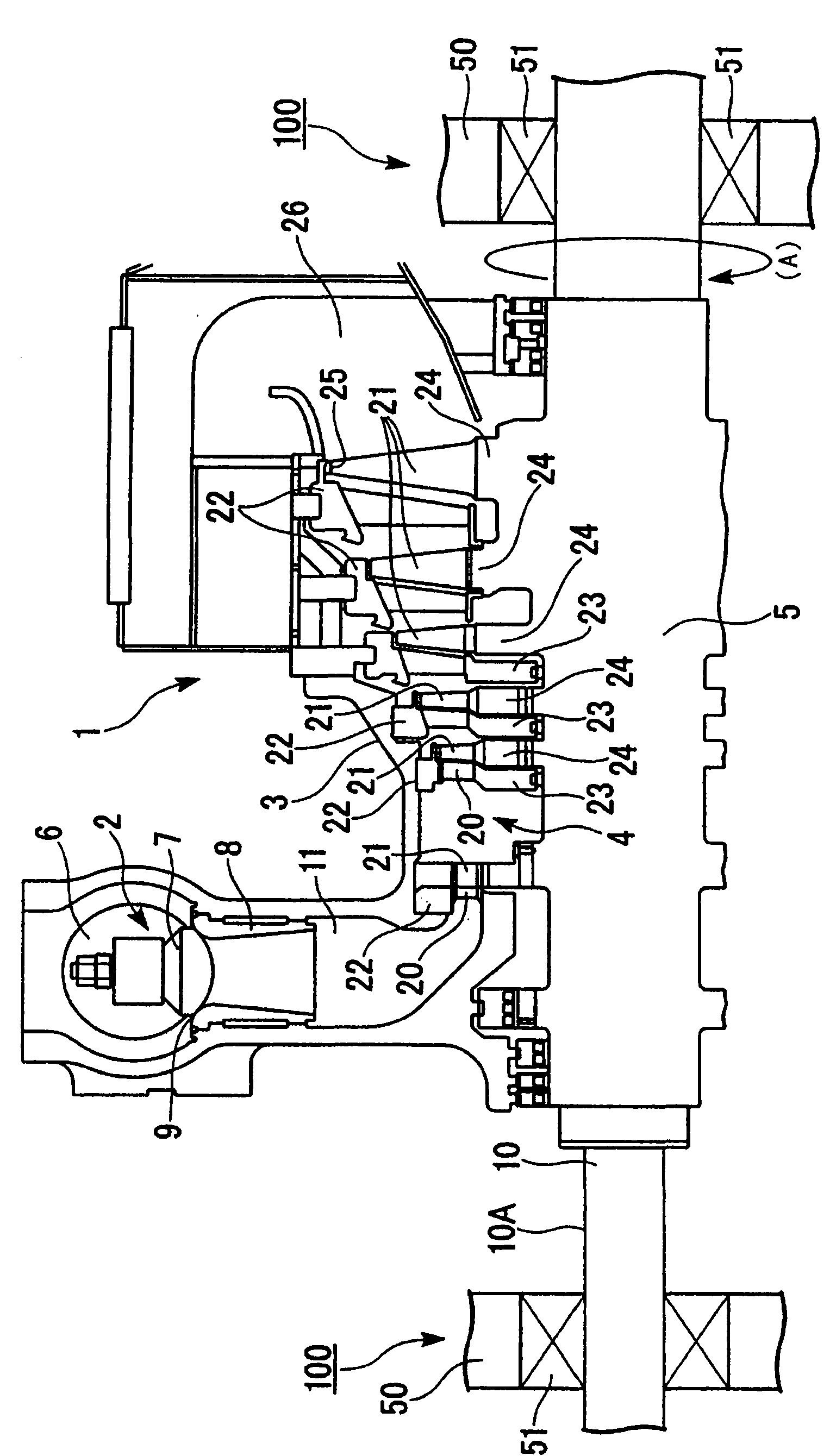
[0053] according to Figure 1 ~ Figure 3 The first embodiment of the present invention will be described. figure 1 A steam turbine 1 is shown as an example of a rotating machine equipped with the bearing device according to the present embodiment. The main structure of the steam turbine 1 includes: a regulating valve 2 for adjusting the amount and pressure of the steam (working fluid) flowing into the steam turbine 1; a casing (casing) 3 for maintaining the pressure; a power generating part 4 for generating power; To the rotor 5 of machines such as compressors.

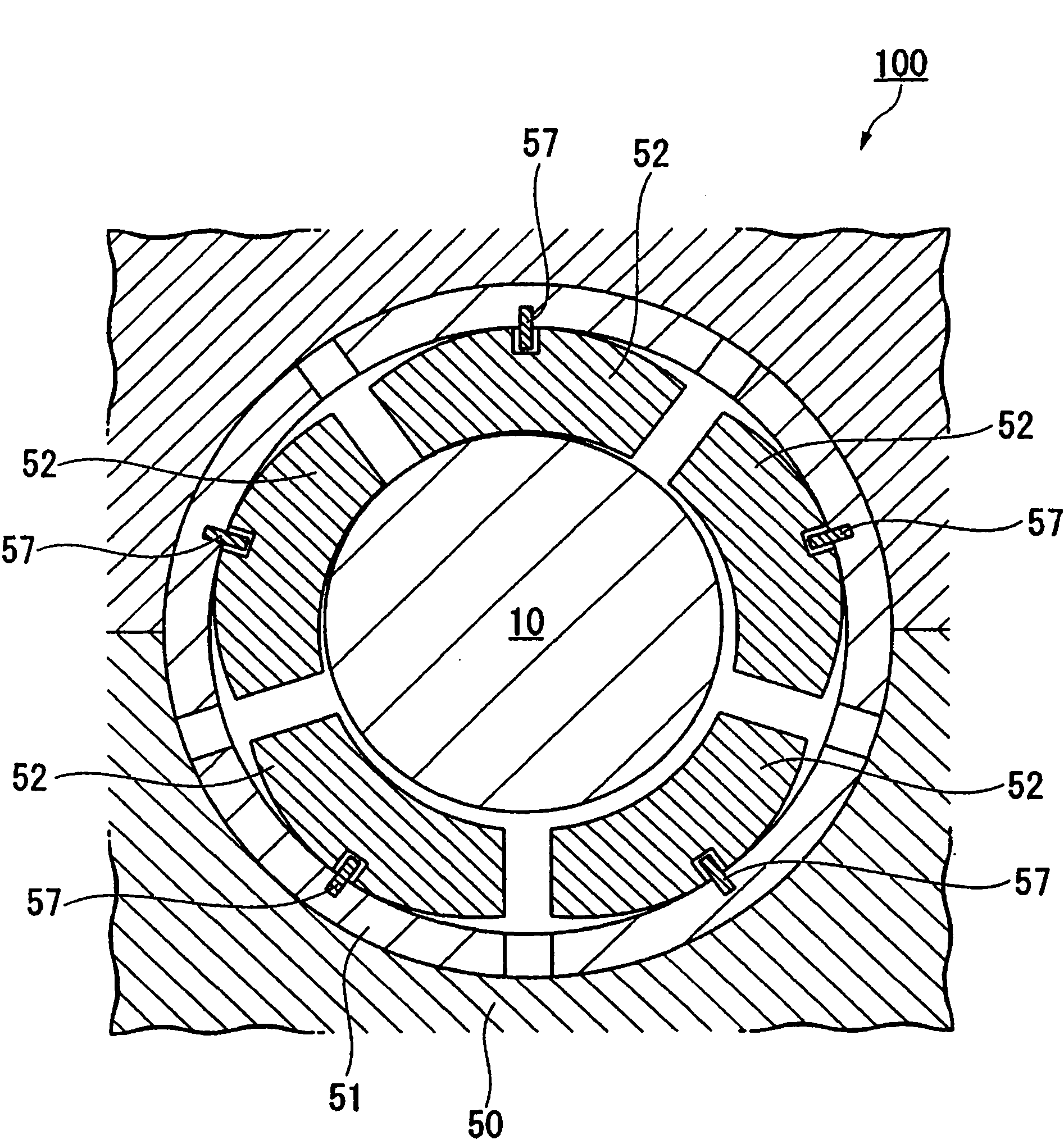
[0054] A plurality of regulating valves 2 are installed inside the housing 3 , and each has a regulating valve chamber 6 , a valve body 7 , and a valve seat 8 through which steam flows from a boiler (not shown). The valve seat 8 is substantially cylindrical, and its axis is perpendicular to that of the rotor 5 . In addition, in the rotor 5, the rotating shaft 10 thereof is supported by a journal bearing device 100...

no. 2 approach

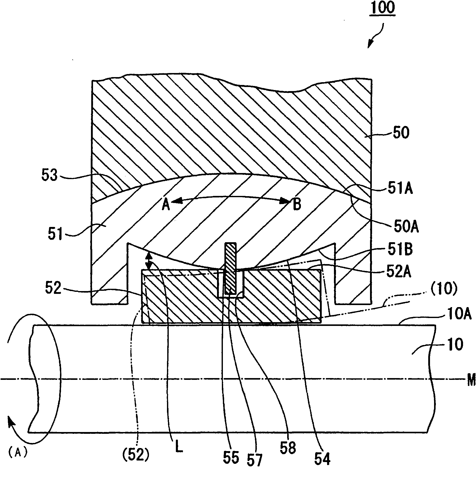
[0070] refer to Figure 6 A second embodiment of the present invention will be described. The structure of the journal bearing device 101 of the present embodiment is different from that of the journal bearing device 100 of the first embodiment in the shape of the inner peripheral surface 51B of the bearing housing 51 . That is, the inner peripheral surface 51B of the bearing housing 51 is a curved surface along the axis M, and the central portion of the curved surface has a shape protruding inward toward the rotating shaft 10 side, and the top of the protruding portion of the curved surface is formed so as to be aligned with the axis M. M is substantially parallel to the flat surfaces 56 .

[0071]Therefore, according to such a journal bearing device 101 , in the normal case where the rotating shaft 10 is not deformed into a bow shape with respect to the axis M thereof, the flat surface 56 at the center of the inner peripheral surface 51B of the bearing housing 51 allows the...

no. 3 approach

[0074] refer to Figure 7 and Figure 8 A third embodiment of the present invention will be described. Such as Figure 7 As shown, the journal bearing device 102 of the present embodiment is different in structure from the journal bearing device 100 of the first embodiment in the position of the pivot shaft 60 which is a supporting member for supporting the pad 52 on the bearing housing 51 . The pivot 60 is arranged such that its base end is fixed to the axial end on the inner peripheral surface 51B side of the bearing housing 51 and its front end protrudes from the inner peripheral surface 51B, and its front end is inserted into an opposing bearing bush. 52 in the recess 61 formed by the outer peripheral surface 52A. Therefore, the bearing bush 52 is positioned relative to the bearing housing 51 in the axial direction and around the shaft (in the direction of the arrow (A)) by the engagement of the pivot shaft 60 and the concave portion 61 . Furthermore, a clearance 62 is...


PUM


Abstract

A bearing device has a bearing housing which is supported by a bearing base mounted to a body of a rotary machine having a rotating shaft and through which the rotating shaft penetrates, and also has pads arranged in the bearing housing so as to circumferentially surround the rotating shaft and rotatably supporting the rotating shaft. The contact surfaces between the outer peripheral surface of the bearing housing and the inner peripheral surface of the bearing base are convex curved surfaces protruding outward along the axis direction of the rotating shaft. The bearing housing is rockably supported by the bearing base via the contact surfaces, or the convex curved surfaces. At least either the inner peripheral surface of the bearing housing or the outer peripheral surface of the pads is a curved surface extending along the axis direction. The distance between the inner peripheral surface of the bearing housing and the outer peripheral surface of the pads gradually increases from the center toward the ends in the axis direction of the bearing housing.

Description

technical field [0001] The present invention relates to a sliding bearing device capable of reducing stress concentration caused by one-end contact, and a rotary machine including the bearing device. Background technique [0002] Conventionally, as such bearing devices, a "pad type journal bearing" disclosed in Patent Document 1 and a "slant pad type bearing" disclosed in Patent Document 2 are known. The bearing devices shown in these patent documents all have a bearing housing and a plurality of bearing pads arranged around the rotating shaft in the bearing housing, wherein the bearing housing is provided so that the rotating shaft as a supported body passes through the center portion of the bearing housing. In addition, in Patent Document 1, two sets of bearing pads arranged around the rotating shaft are provided along the axial direction of the rotating shaft. [0003] Patent Document 1: JP-A-62-118114 [0004] Patent Document 2: Shikaihei No. 5-42744 [0005] However,...

Claims


Application Information

Patent Timeline
Patent Type & Authority Applications(China)
IPC IPC(8): F16C23/04F01D25/16F16C17/03
CPCF16C17/03F16C23/04F01D25/16F16C2360/00
Inventor 平井孝昌高桥定池野恭一长井直之
Owner MITSUBISHI HEAVY INDUSTIES COMPRESSOR CORP
Why Eureka
Try Eureka