
Oil seal

An oil seal and sealing lip technology, which is applied to engine components, engine seals, mechanical equipment, etc., can solve the problems of bad sealing effect, easy roll-up operability of the sealing lip 100, and difficulty in forming, so as to improve the sealing performance, Improves fluid lubrication effect, reduces sliding torque and sliding heat generation

Inactive Publication Date: 2010-12-29
NOK CORP
View PDF1 Cites 6 Cited by
  • Summary
  • Abstract
  • Description
  • Claims
  • Application Information

AI Technical Summary

Problems solved by technology

[0007] However, in the method of reducing the urging force on the rotating shaft 200 by reducing the cross-sectional area of ​​the sealing lip 100, since the rigidity of the sealing lip 100 is reduced, the clamping coil spring 105 is easy to fall off and is inserted into the rotating shaft 200. Problems with poor operability such as sealing lip 100 is easy to roll up
In addition, when the material is changed to a low-friction material and the surface treatment is used to achieve low friction, there are problems such as bad influence on sealing performance and difficulty in molding.

Method used


Image

  • Oil seal
  • Oil seal
  • Oil seal

Examples


Embodiment Construction

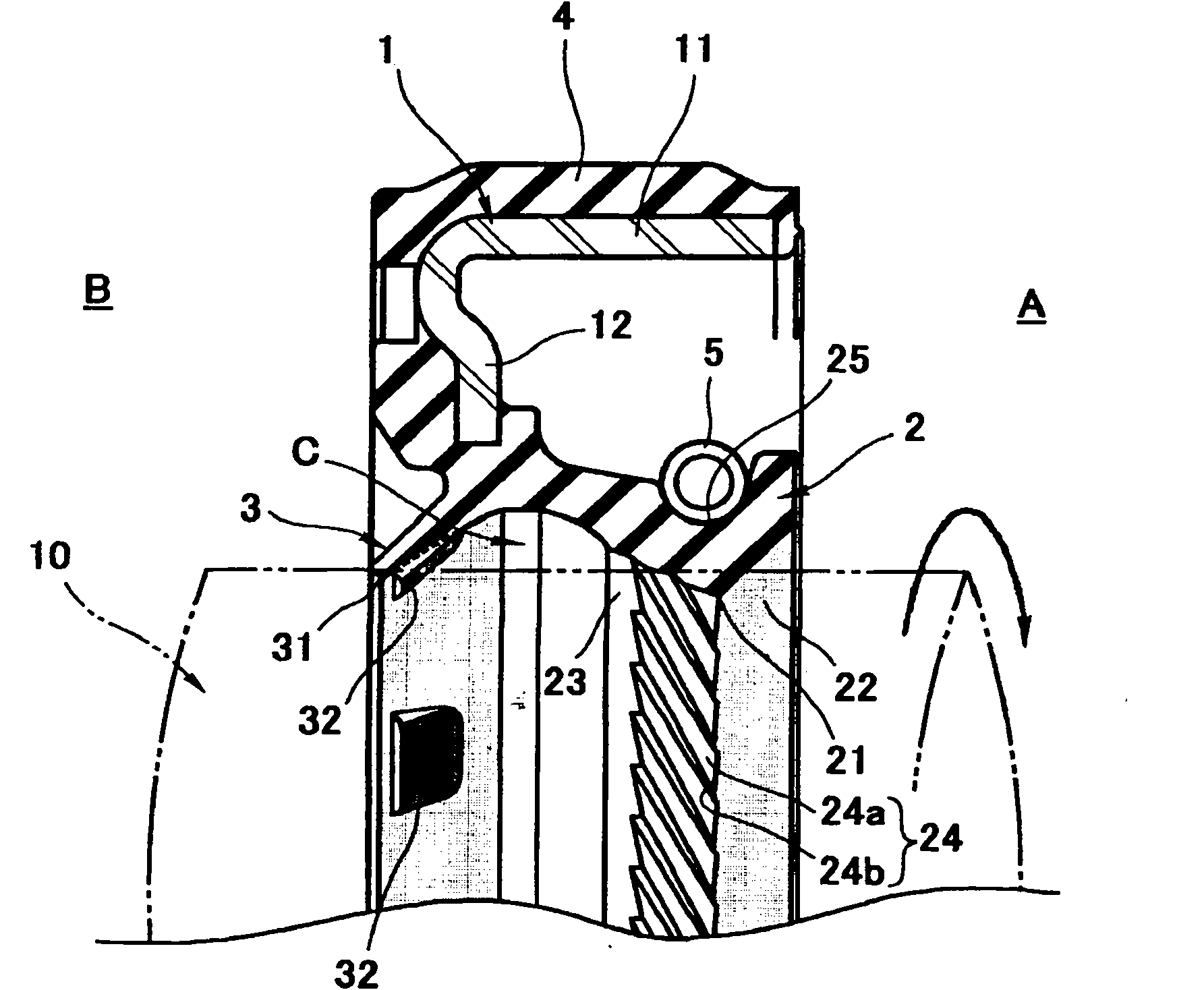
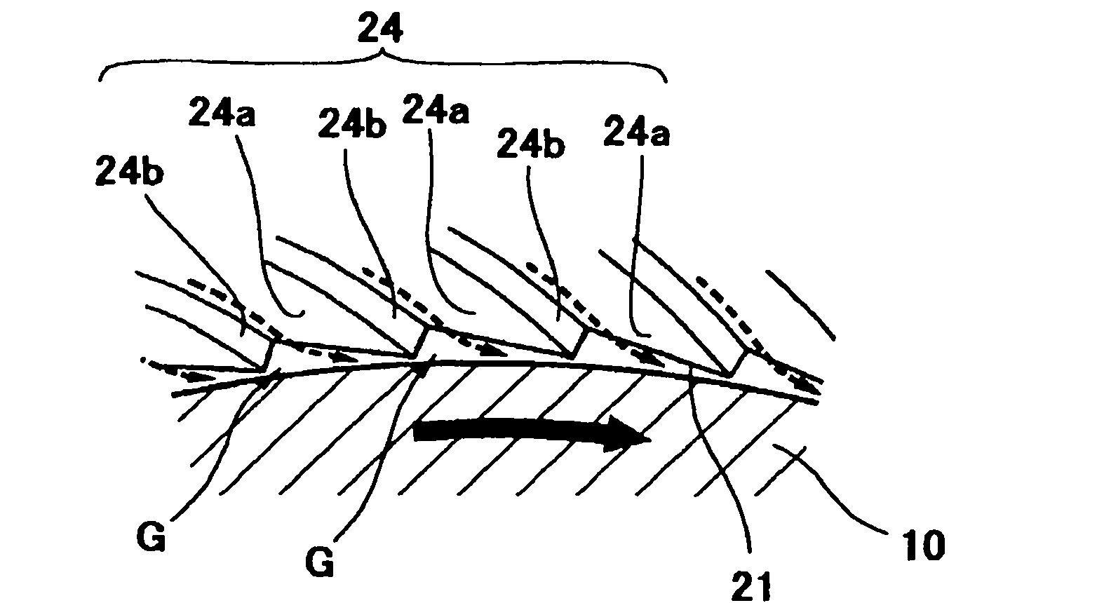
[0044] Hereinafter, a preferred embodiment of the oil seal of the present invention will be described with reference to the drawings. First of all, figure 1 It is a single-sided cross-sectional view of the first embodiment of the oil seal of the present invention taken with a plane passing through the axis, figure 2 It is an explanatory diagram showing the shape and function of the uneven stripe of the sealing lip of the first embodiment.

[0045] figure 1 The oil seal shown in the metal ring 1 is integrally provided with a sealing lip 2, a dust-proof lip 3, and a fixed sealing portion 4. The sealing lip 2, the dust-proof lip 3 and the fixed sealing portion 4 on the outer peripheral side are made of a rubber-like elastic material and connected to each other. In addition, a clamping coil spring 5 is mounted on the outer peripheral surface near the front end of the sealing lip 2.

[0046] The metal ring 1 is a press-formed product such as a steel plate, and has an outer periphera...


PUM


Abstract

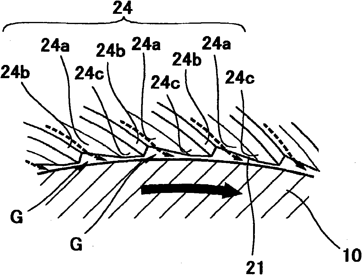
Ridge and groove sections (24) are formed at a predetermined circumferential pitch on at least either of a slide seal surface (21) and an atmosphere-side circular conical surface (23) of a seal lip (2). Each of the ridge and groove sections (24) has a first slope surface (24a) and a second slope surface (24b). The first slope surface (24a) slopes at a gentle gradient toward the rotation direction of a rotation body (10) and in the direction in which the distance between the first slope surface (24a) and the outer peripheral surface of the rotation body (10) decreases. The second slope surface (24b) rises at a steeper gradient than the first slope surface (24a) from the decreased distance portion. As the rotation body (10) rotates, a portion of fluid to be sealed introduced into a gap between the rotation body (10) and the ridge and groove sections (24) enters like a wedge into the gap toward the decreased distance portion to generate dynamic pressure. This forms a thick fluid lubrication film to reduce slide resistance between the seal lip and the outer peripheral surface of the rotation body (10).

Description

Technical field [0001] The present invention relates to an oil seal that seals the outer circumference of a rotating body in automobiles, general machines, industrial machines, etc. through a sealing lip. Background technique [0002] As a typical prior art of an oil seal, an oil seal described in Patent Document 1 below is known. [0003] Patent Document 1: Japanese Patent Application Publication No. 2005-282841 [0004] Figure 7 This is a single-sided cross-sectional view of a conventional oil seal having the same configuration as that of Patent Document 1 taken on a plane passing through the axis. The oil seal has a sealing lip 100 formed of a rubber-like elastic material. On the inner peripheral surface of the sealing lip 100, a sealing space side cone that becomes a large diameter toward the sealing space A side is formed on the inner peripheral surface of the sealing lip 100 with the smallest diameter lip 101 as a boundary The surface 102 and the atmospheric-side conical surf...

Claims


Application Information

Patent Timeline
IPC IPC(8): F16J15/32F16J15/3244
CPCF16J15/3244F16J15/324
Inventor 中川岳洋
Owner NOK CORP
Learn More