Machining tool for brake drum

A brake drum and tooling technology, applied in the field of mechanical processing, can solve problems such as high scrap rate, reduced shift output, and difficulty in ensuring beating, and achieve the effect of stable output

Inactive Publication Date: 2011-01-05
溧阳市虹翔机械制造有限公司
View PDF0 Cites 7 Cited by
  • Summary
  • Abstract
  • Description
  • Claims
  • Application Information

AI Technical Summary

Problems solved by technology

However, in the process of processing, the cylindricity and smoothness of the braking surface are often caused by reasons such as vibration of the knife, and the runout with the reference hole B and reference surface C is also difficult to guarantee. In order to ensure the 0.05 runout between the braking surface and the φ300 outer circle, It is also necessary to control the tolerance of the φ300 outer circle within the range of 0.025, which virtually increases the scrap rate of the front line and reduces the shift output
This processing method has a high scrap rate and a low shift output, which urgently needs to be improved.

Method used


Image

  • Machining tool for brake drum
  • Machining tool for brake drum
  • Machining tool for brake drum

Examples


Embodiment Construction

[0014] The technical solution will be further described below in conjunction with the accompanying drawings and specific embodiments.

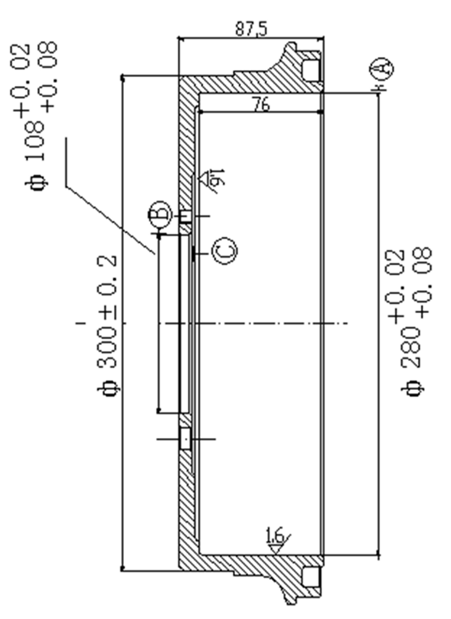
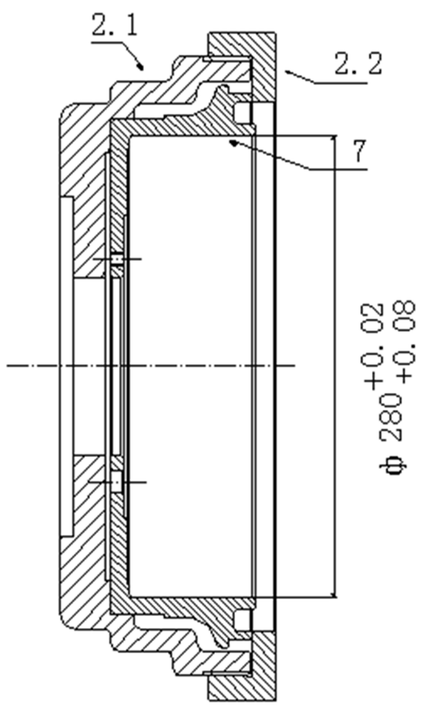
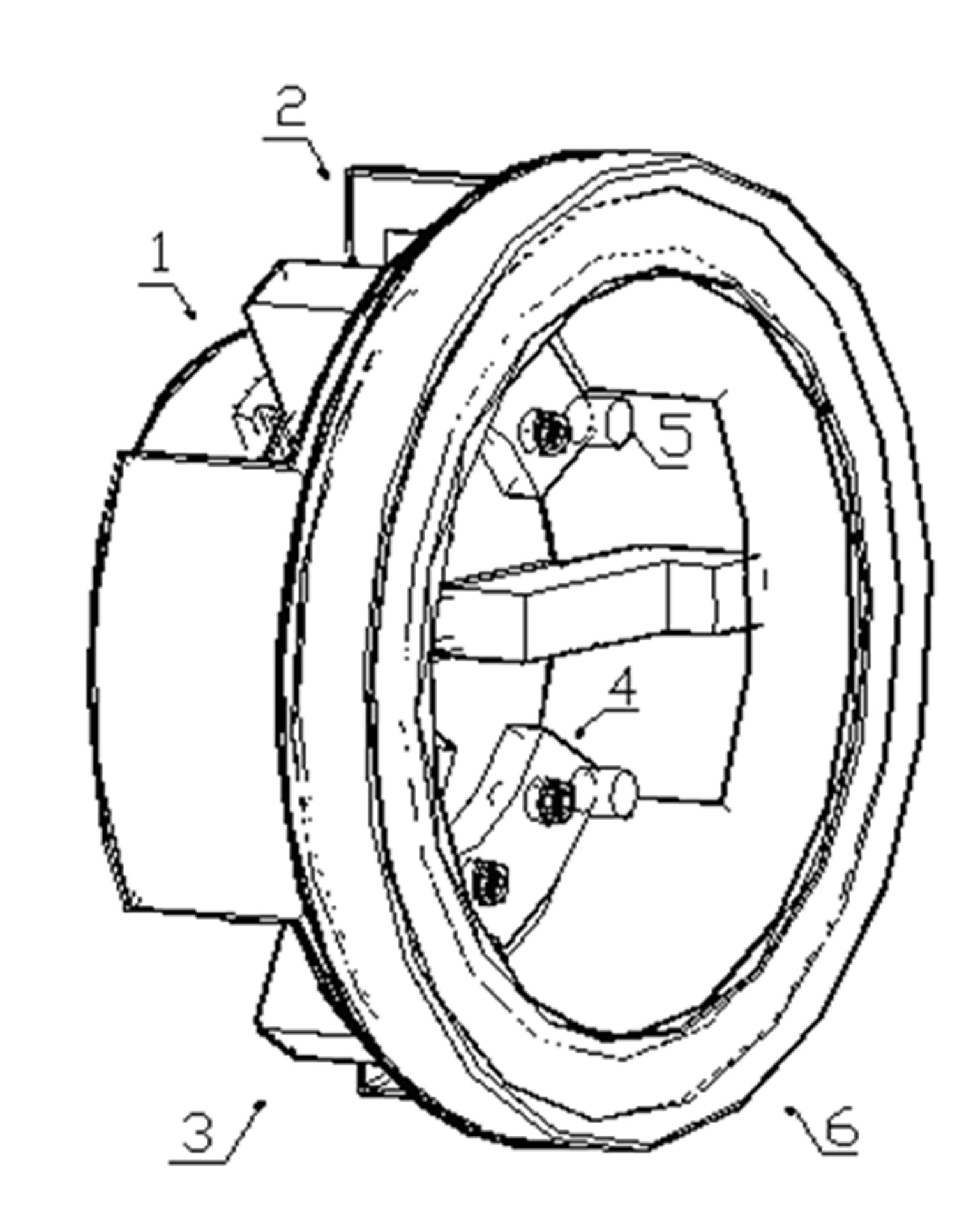
[0015] A brake drum processing tool, comprising a three-jaw chuck 1 and a locking cap 6; the axis of the locking cap 6 is the same as that of the three-jaw chuck 1; the locking cap 6 and the three-jaw The disc body of the chuck 1 is connected by the half cover 2; the shape of the space surrounded by the locking cap 6, the disc body of the three-jaw chuck 1 and the half cover 2 corresponds to the shape of the brake drum 7 to be processed; the three The surface of the jaw chuck 1 is provided with positioning posts 5 corresponding to the screw holes on the processed brake drum 7 .

[0016] The half cover 2 is provided with three gaps, and the three claws 3 of the three-jaw chuck 1 are correspondingly arranged therein; the bottom of the half cover 2 is connected with the disc body of the three-jaw chuck 1 through three connecting plates.

[0017]...


PUM


Abstract

The invention discloses a machining tool for a brake drum. The machining tool comprises a three jaw chuck and a locking cap, wherein the axis of the locking cap is the same as that of the three jaw chuck; the locking cap is connected with the body of the three jaw chuck through a half sleeve; a space enclosed by the locking cap, the body of the three jaw chuck and the half sleeve has a shape corresponding to the appearance of a machined brake drum; and the surface of the body of the three jaw chuck is provided with positioning columns corresponding to screw holes on the machined brake drum. Through experimental production, the entire production line has stable quality and stable yield after the bottleneck problem of a lathed braking surface is solved.

Description

technical field [0001] The invention belongs to the technical field of mechanical processing, in particular to a brake drum processing tool. Background technique [0002] In the prior art, for automobile brake drums (such as figure 1 ) processing, the requirements for the beating, cylindricity and smoothness of the braking surface of the brake drum are relatively high. The processing state in the prior art is as figure 2 As shown, first process the φ300, bottom plane and φ108 hole of the brake drum, and then use the φ300 outer circle to position the upper mandrel to process the braking surface. However, in the process of processing, the cylindricity and smoothness of the braking surface are often caused by reasons such as vibration of the knife, and the runout with the reference hole B and reference surface C is also difficult to guarantee. In order to ensure the 0.05 runout between the braking surface and the φ300 outer circle, It is also necessary to control the tolera...

Claims


Application Information

Patent Timeline
Patent Type & Authority Applications(China)
IPC IPC(8): B23B31/10
Inventor 吕燕翔吕伟龙史仁龙万传友彭芳美周国忠
Owner 溧阳市虹翔机械制造有限公司
Why Eureka
Try Eureka