
Grinding disc and high-speed rail bridge grinder provided with same

A grinding machine and grinding disc technology, which is applied to machine tools, grinding/polishing equipment, grinding machines, etc., which are suitable for grinding workpiece planes, and can solve problems such as the easy breakage of the positioning pin of the grinding block, the influence of the lower knife, and the easy upward jump of the machine.

Inactive Publication Date: 2011-01-05
何轩
View PDF10 Cites 10 Cited by
  • Summary
  • Abstract
  • Description
  • Claims
  • Application Information

AI Technical Summary

Problems solved by technology

[0007] First, when the entire grinding disc is consumed, it is necessary to re-order the grinding disc from the manufacturer of the grinding machine. On the one hand, the discarded grinding disc body will be counted as cost expenditure. On the other hand, the grinding machine manufacturer also needs to purchase grinding blocks from the diamond product manufacturer. Invisibly adding a link means adding a part of the cost, resulting in high cost of use
[0008] Second, because the grinding block is close to the disc body, when the grinding block wears to the end, the disc body of the grinding disc will touch the processing surface, causing it to be easily damaged by friction
[0009] Third, the high-temperature welding grinding block not only carbonizes the diamond, reduces the grinding ability, and shortens the service life, but also the high temperature is easy to cause the deformation of the disc body, which affects the balance. Uneven, unsatisfactory sanding effect
[0010] In this regard, split grinding discs came into being, but the positioning device design of conventional split grinding discs is not scientific enough to ensure absolute positioning, and the positioning pin of the grinding block is easy to break. The sharpness of the product is not enough, the sound of grinding is screaming and harsh, the machine is easy to jump upwards, the work efficiency is too low, and the work mood of the workers is affected

Method used


Image

  • Grinding disc and high-speed rail bridge grinder provided with same
  • Grinding disc and high-speed rail bridge grinder provided with same
  • Grinding disc and high-speed rail bridge grinder provided with same

Examples


Embodiment Construction

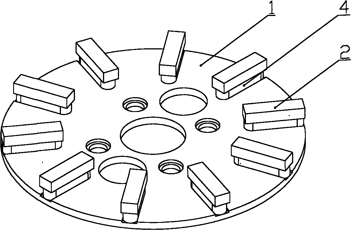
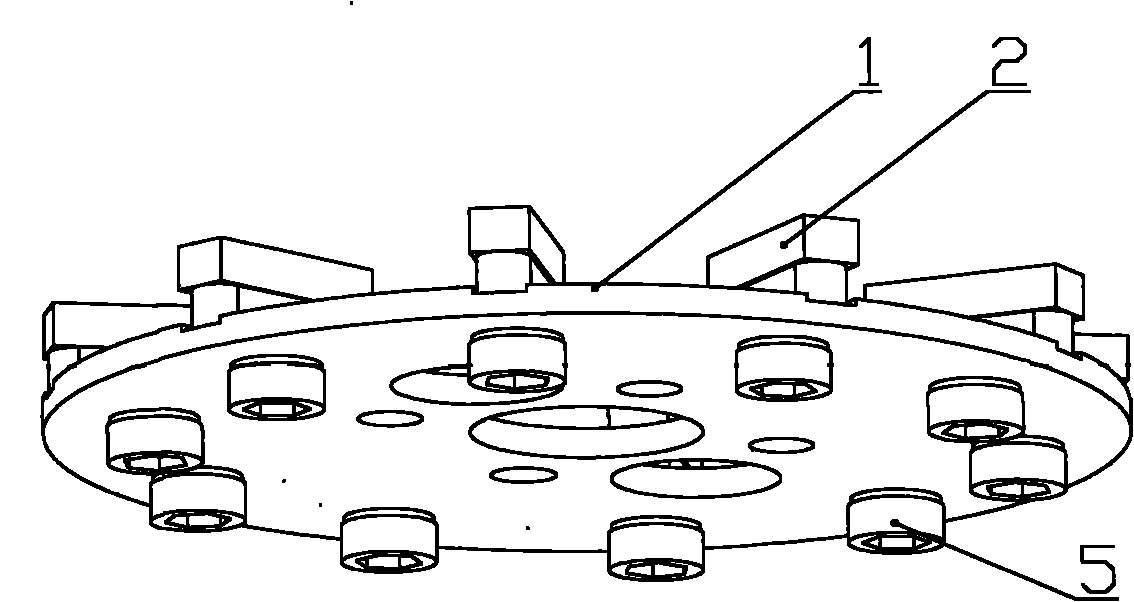
[0039] The core of the invention is to provide a grinding disc. The grinding disc adopts a split design, no welding is required between the grinding block and the disc body, the installation is simple, and the operation is convenient. When the grinding block is completely worn out, only the grinding block needs to be replaced instead of the disc body, which saves costs; The wear of the disc body prevents the sliding of the grinding block to the greatest extent and ensures the effective working performance of the grinding block. Another core of the present invention is to provide a high-speed rail bridge grinding machine provided with the above-mentioned grinding disc.

[0040] In order to enable those skilled in the art to better understand the solution of the present invention, the present invention will be further described in detail below in conjunction with the accompanying drawings and specific embodiments.

[0041] The words "upper, lower, inner, outer" in this article ...


PUM


Abstract

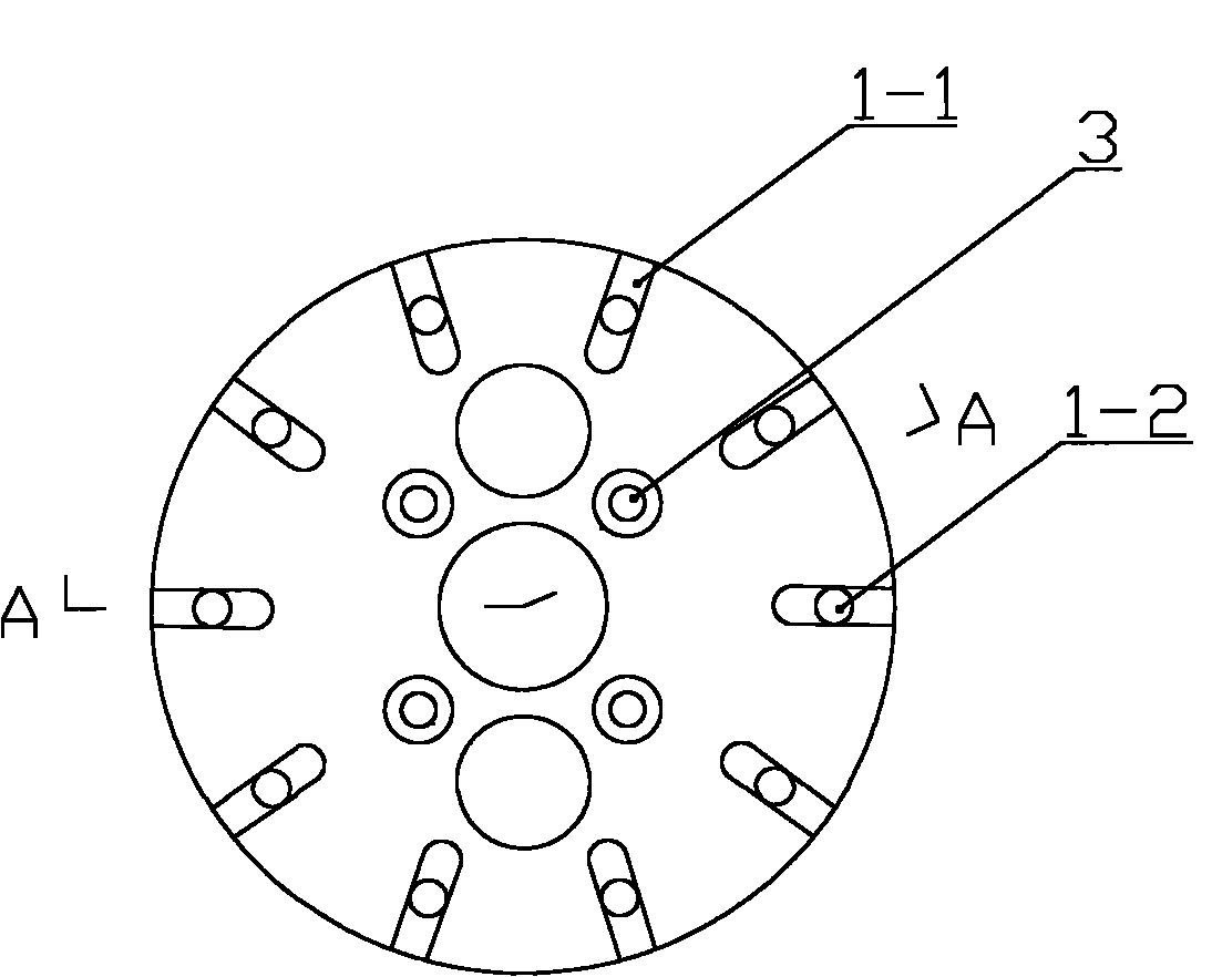
The invention discloses a grinding disc for a high-speed rail bridge grinder. The grinding disc comprises a disc body, a grinding block and an anti-slip key, wherein the grinding block is arranged on the disc body; the disc body is provided with an anti-slip groove; the anti-slip key is embedded in the anti-slip groove and fixed with the disc body relatively; the grinding block is fixed on the top of the anti-slip key; the anti-slip key is provided with a screw hole; the bottom of the anti-slip groove of the disc body is provided with a corresponding positioning hole; and the anti-slip key is connected with the disc body through a screw. The grinding block and the disc body of the grinding disc do not need to be welded and are easy to install and convenient to operate; when the grinding block is fully worn, only the grinding block instead of the disc body needs to be replaced, so that cost is saved greatly; simultaneously, the disc body can be effectively prevented from being worn, the grinding block is prevented from sliding to the maximum extent and the effective working performance of the grinding block is ensured. The invention also discloses the high-speed rail bridge grinder provided with the grinding disc.

Description

technical field [0001] The invention relates to the technical field of bridge grinding, in particular to a matching grinding disc of a high-speed railway bridge grinding machine. The present invention also relates to a high-speed rail bridge grinding machine provided with the above-mentioned grinding disc. Background technique [0002] With the rapid development of domestic high-speed railway (referred to as high-speed railway) construction, the high-speed railway bridge project has reached a considerable scale. [0003] High-speed trains have extremely high requirements on the smoothness of the bridge concrete top surface. However, it is often difficult to meet the design requirements due to various factors during the construction process. When the flatness of the bridge surface cannot meet the required error requirements, additional remedial measures must be taken to deal with and repair the bridge top surface defects in order to meet the design requirements. required qu...

Claims


Application Information

Patent Timeline
IPC IPC(8): B24D7/06B24B7/00
Inventor 何轩
Owner 何轩
Learn More