
Flow channel clamp

A fixture and runner technology, used in manufacturing tools, manipulators, program-controlled manipulators, etc., can solve the problems of difficulty, increased runner removal, and the lack of integration of sensors and fixture bodies, achieving compact size and large clamping force. Effect

Inactive Publication Date: 2011-01-05
STAR SEIKI XIANGYANG
View PDF4 Cites 2 Cited by
  • Summary
  • Abstract
  • Description
  • Claims
  • Application Information

AI Technical Summary

Problems solved by technology

[0002] At present, with the improvement of factory automation, more and more take-out manipulators are used in injection molding. However, the requirements for compact mold structure and saving raw materials are getting higher and higher, so that the parts that can be clamped by the flow channel are getting smaller and smaller. This increases the difficulty of taking out the runner and affects the automatic production effect
However, the existing runner fixtures are relatively large, and the sensor for realizing whether there is no confirmation in the runner clamp is not integrated with the fixture body, which cannot meet the needs of automation

Method used


Image

  • Flow channel clamp
  • Flow channel clamp
  • Flow channel clamp

Examples


Embodiment Construction

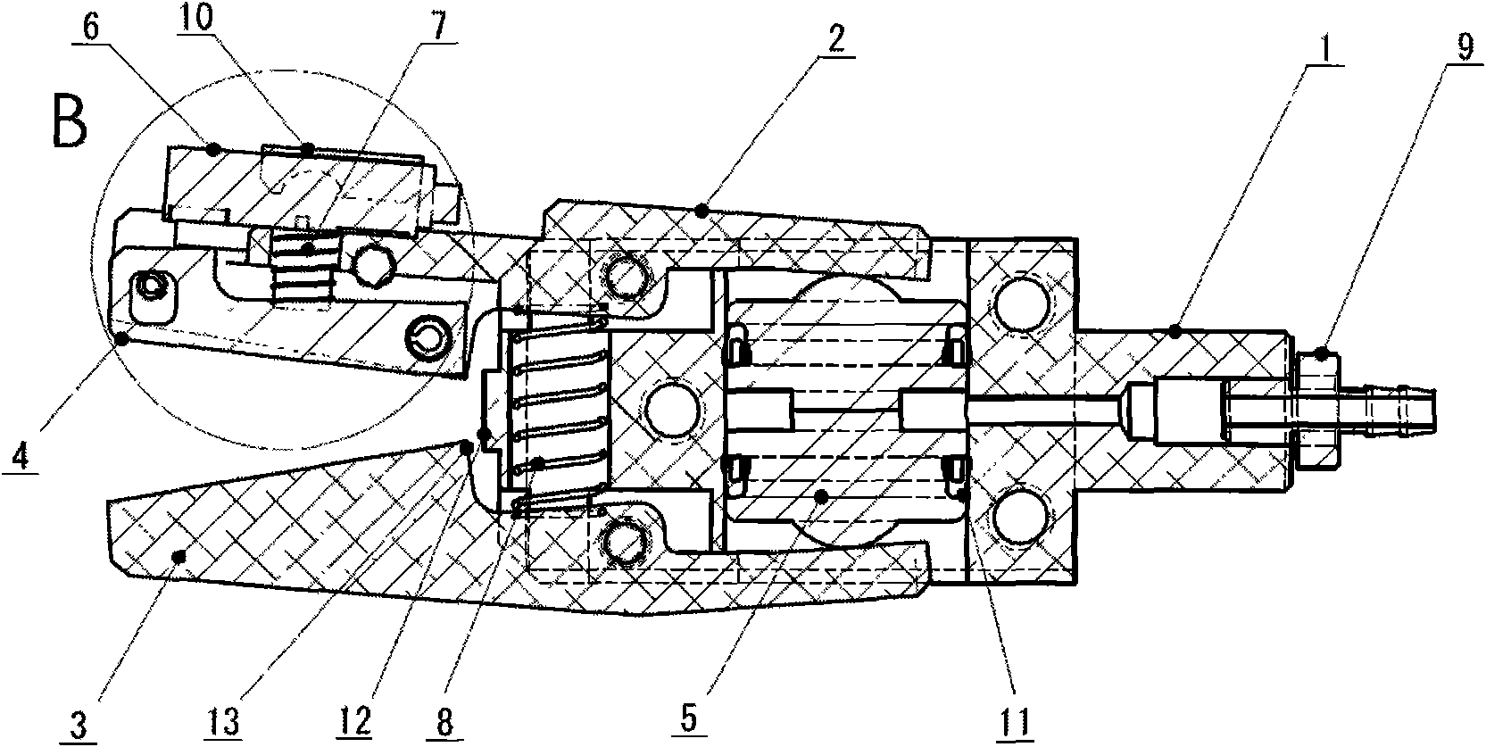
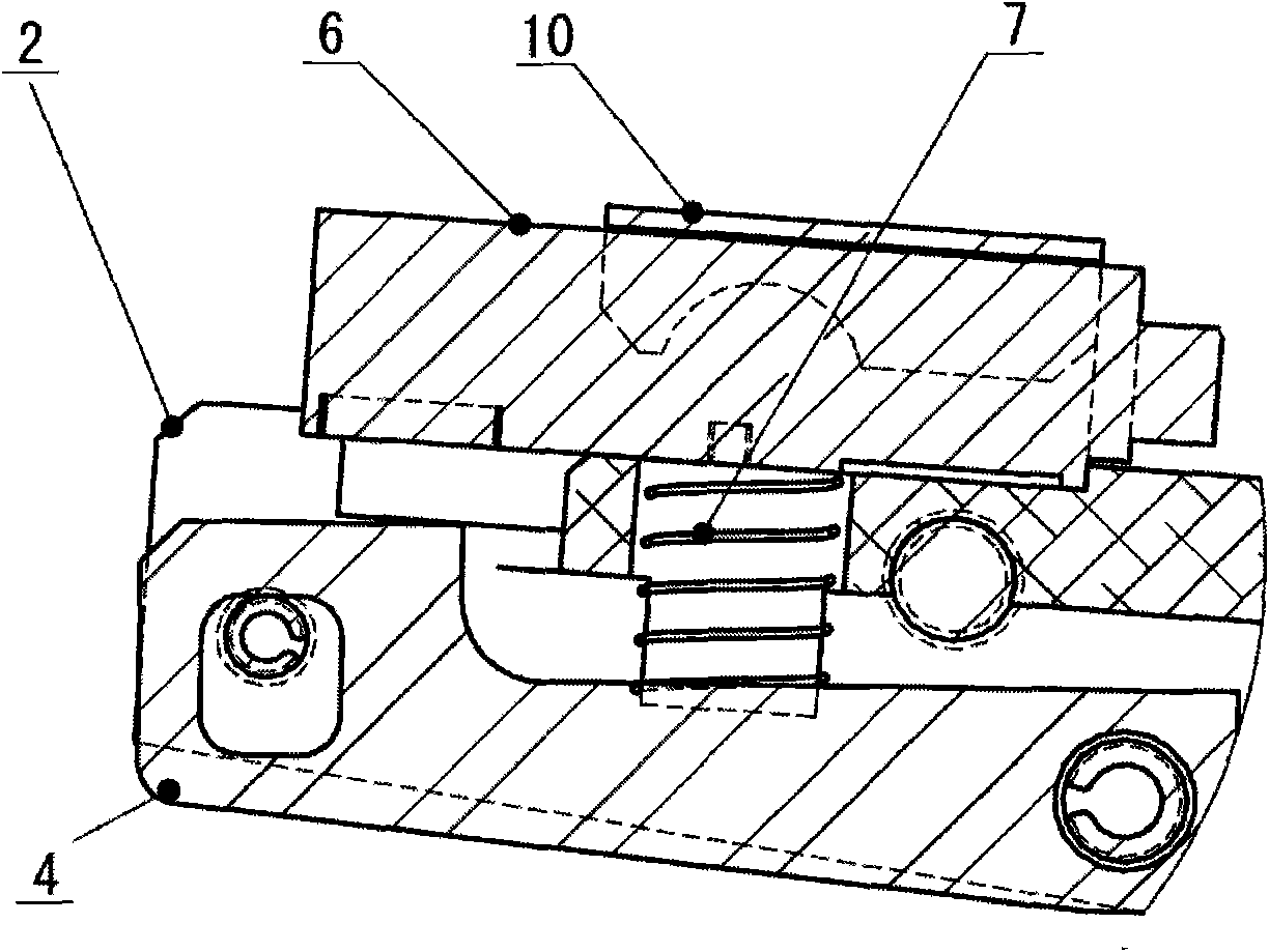
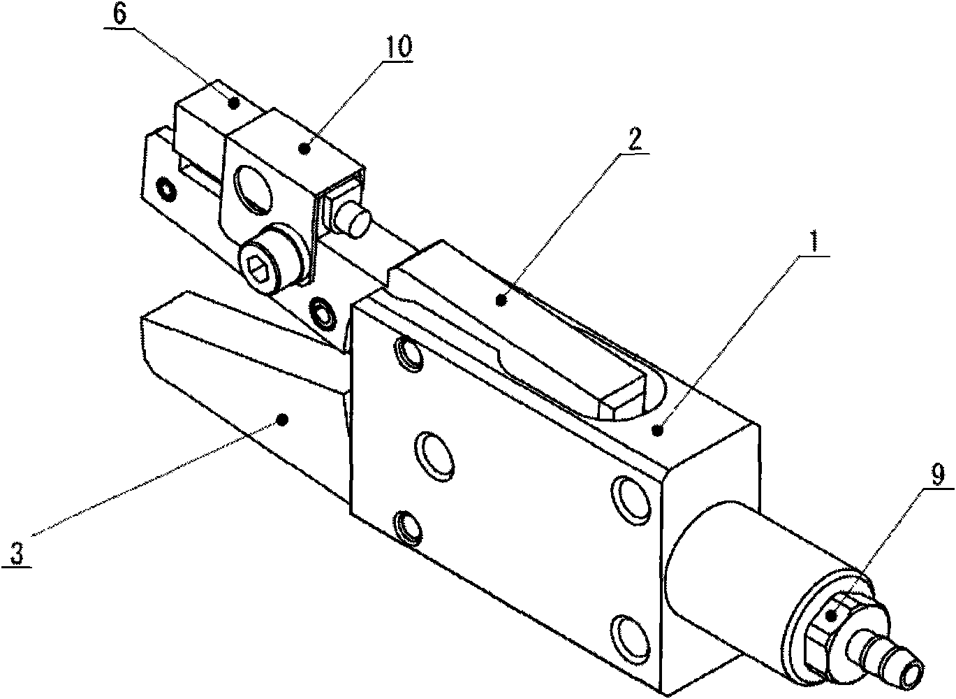
[0011] Such as figure 1 , figure 2 , image 3 As shown, the clamp base 1 adopts an external structure combining a cuboid and a cylinder, so that two connection methods of screw and clamping the cylinder can be used, and its small shape is guaranteed; the clamp claw 2 on the sensor side and the clamp claw 3 are respectively The revolving pin is connected with the fixture base 1, and the two fixture claws can rotate around the revolving pin. The two fixture claws are designed to be flat, and shavings are made on the clamping surface to facilitate various flow channels of the fixture; the sensor 6 is installed on the sensor side of the fixture claw 2 on the sensor fixing frame 10; two pistons 5 are arranged in the cavity of the fixture base 1, and the pistons are oblong in design, which increases the force-bearing area without increasing the thickness of the fixture to obtain greater clamping force , the arc surfaces of the two pistons 5 are in contact with the clamp claw 2 an...


PUM


Abstract

The invention relates to a flow channel clamp for taking an injection molding product out of a flow channel by a manipulator. A sensor side clamp claw, a clamp claw and a clamp substrate are movably connected; a sensor is arranged on a fixing bracket; two pistons are arranged in the cavity of the clamp substrate; the cambered surfaces of the two pistons are contacted with the two clamp claws; return springs are sleeved on inner shafts of two clamp claw holes; an air inlet joint is arranged at one end of the clamp substrate; the clamping position of the sensor side clamp claw is provided with an induction tongue connected with the sensor; a spring is arranged in the sensor side clamp claw and arranged between the induction tongue and an inductor; one end of the clamp substrate is provided with a limiting boss; and the clamping claw is provided with a limiting surface. When the flow channel clamp is used, an air pressure in the substrate pushes the two clamp claws through the piston so as to realize gripping; and when the clamp clamps the flow channel, the induction tongue approaches the inductor, so that the inductor starts working and sends a confirmation signal to the manipulator. The clamp has the advantages of small size, large clamping force, convenience for installation under the condition of small space and taking various flow channels at positions which can be clamped out, capability of giving feedback information to the manipulator and realization of confirmation of the existence and absence of flow channel clamping.

Description

technical field [0001] The invention relates to a fixture in the field of mechanical manufacturing, in particular to a clamping device for taking out flow channels of injection molded products by manipulators. Background technique [0002] At present, with the improvement of factory automation, more and more take-out manipulators are used in injection molding. However, the requirements for compact mold structure and saving raw materials are getting higher and higher, so that the parts that can be clamped by the flow channel are getting smaller and smaller. This increases the difficulty of taking out the runner, which affects the automatic production effect. However, the existing runner fixtures are relatively large, and the sensor for realizing whether the runner is clamped or not is not integrated with the fixture body, which cannot meet the needs of automation. Contents of the invention [0003] In order to solve the deficiencies of the prior art, the purpose of the pre...

Claims


Application Information

Patent Timeline
Patent Type & Authority Applications(China)
IPC IPC(8): B29C45/40B25J9/00
Inventor 水野耕治姚荣
Owner STAR SEIKI XIANGYANG
Learn More