
Glass bead forming machine

A glass bead and mechanical technology, used in glass forming, glass manufacturing equipment, manufacturing tools, etc., can solve the problems of complex structure, damage to forming molds, low processing efficiency and enlarge production requirements, and achieve the effect of concise structure

Inactive Publication Date: 2011-01-05
常熟市沙家浜镇建国玻璃模具厂
View PDF6 Cites 0 Cited by
  • Summary
  • Abstract
  • Description
  • Claims
  • Application Information

AI Technical Summary

Problems solved by technology

Although these two patents can be used to produce glass beads, they both have complex structures and low processing efficiency, which are not enough to meet the requirements of industrial scale-up production.
Especially the former patent scheme in above-mentioned two patent schemes can cause serious waste of energy
In addition, the glass bead molding mold needs to be cooled during the glass bead molding process, otherwise it will damage the molding mold and affect the molding efficiency
That is to say, as a glass bead forming machine, if there is a lack of cooling measures for the forming mold or unreasonable cooling measures, it is difficult to put the glass bead forming machine into practice.
However, the prior art does not provide this kind of enlightenment. For this reason, the applicant has carried out beneficial attempts and found a solution to the problem. The technical solution to be introduced below is produced under this background

Method used


Image

  • Glass bead forming machine
  • Glass bead forming machine

Examples


Embodiment Construction

[0008] In order to enable the examiners of the patent office, especially the public, to understand the technical essence and beneficial effects of the present invention more clearly, the applicant will describe in detail below in conjunction with the accompanying drawings in the form of embodiments, but none of the descriptions of the embodiments is a description of the present invention. Restriction of the inventive solution, any equivalent transformation made according to the concept of the present invention which is only in form but not in substance shall be regarded as the scope of the technical solution of the present invention.

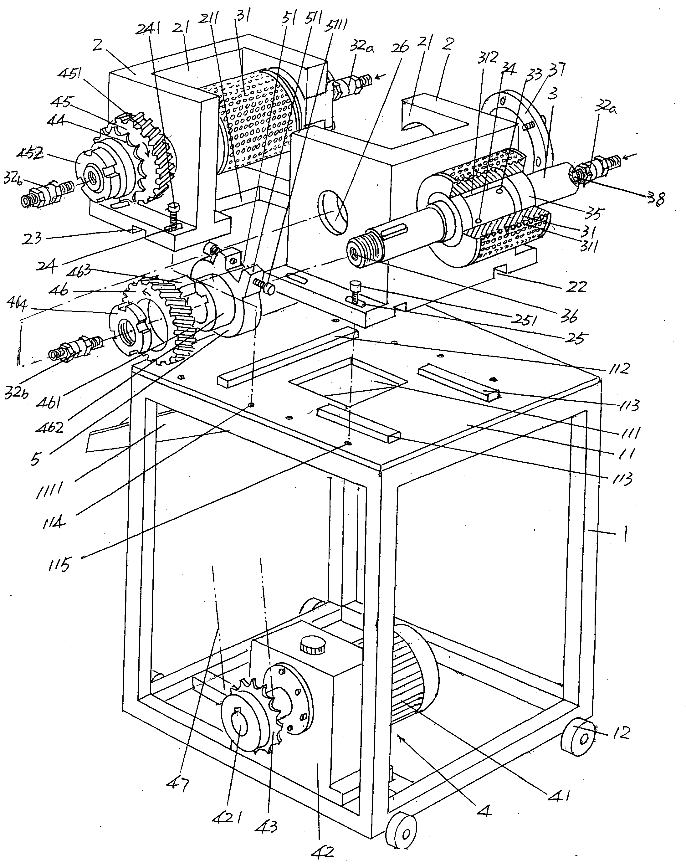
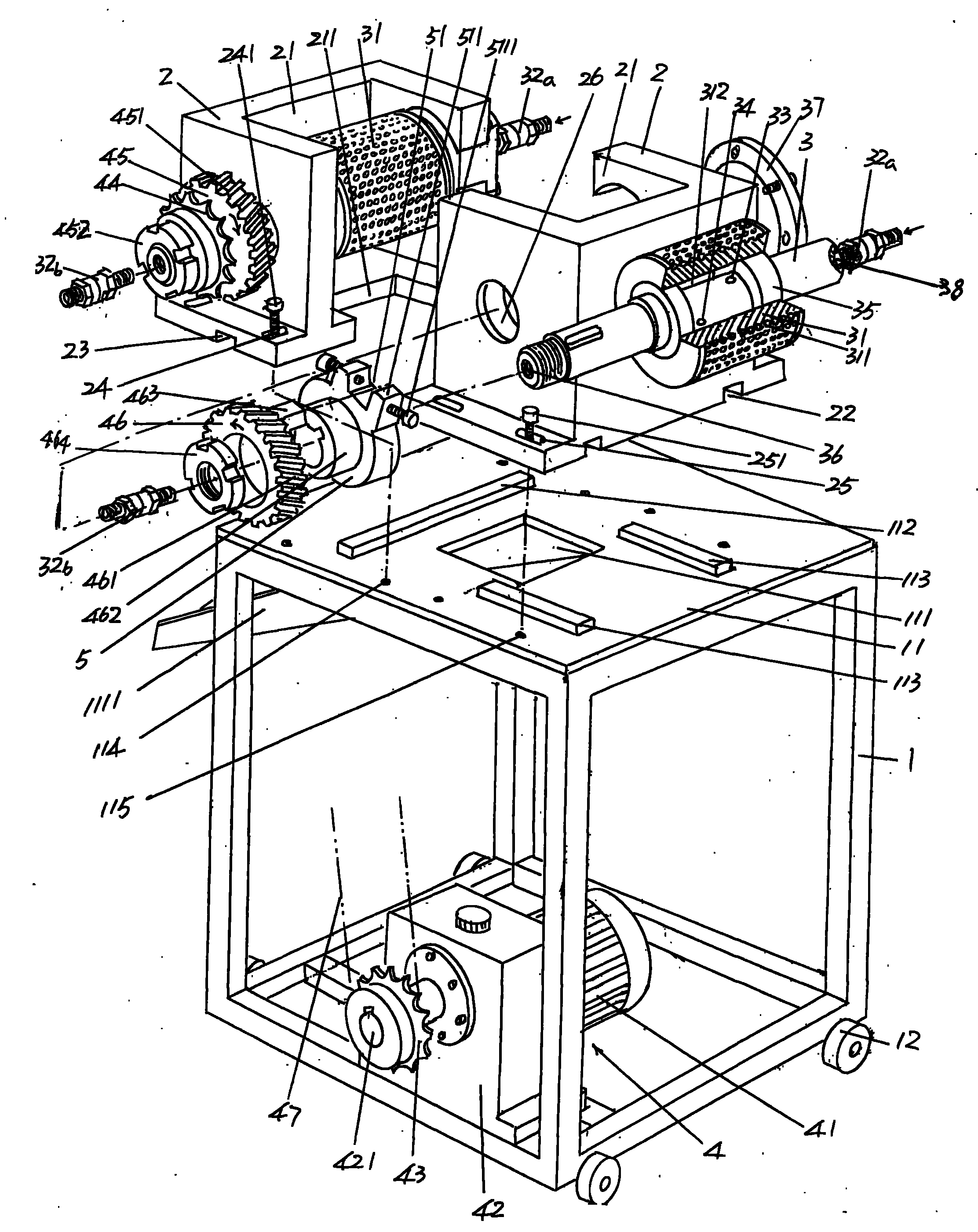
[0009] please see figure 1 , a frame 1 whose details are not limited by the illustration is given. The details referred to here refer to setting a sealing plate on one side of the frame 1, or slightly changing the geometric shape of the frame 1 in form. ,wait. In a preferred solution, a switch box (also called an electrical box) may be provided...


PUM


Abstract

The invention relates to a glass bead forming machine belonging to the field of glass product forming machines. The glass bead forming machine comprises a stand, a pair of mould shaft seats, a pair of mould shafts and a power transmission mechanism, wherein the top of the stand forms a stand platform, and the stand platform is provided with a discharge opening, a longitudinal guide rail and a horizontal guide rail; the pair of mould shaft seats are respectively provided with mould containing cavities and matched face to face, and the bottoms of the mould containing cavities are provided with discharge cavities; the pair of mould shafts are respectively fixedly provided with glass bead forming moulds; the power transmission mechanism is arranged on the stand and connected with the pair of mould shafts; one ends of the pair of mould shafts are respectively matched and connected with water inlet flexible joints, and the other ends thereof are respectively matched and connected with water outlet flexible joints; a water discharge hole and a water return hole are arranged in the middles of the pair of mould shafts; and water cooling cavities are formed between the inner walls of the glass bead forming moulds and the outer walls of the middles of the pair of mould shafts. The invention is simple in structure and can meet the requirements on industrialized batch production by efficiently forming glass beads and ensure the service life and the forming efficiency.

Description

technical field [0001] The invention belongs to the technical field of glass product forming machinery, and in particular relates to a glass bead forming machine. Background technique [0002] Glass beads belong to the category of glass balls. However, they are called beads because they are relatively small in diameter, and the common diameters are like rapeseed, fish eggs or pearls of river mussels. Glass beads have a crystal clear decorative effect and are widely used in but not limited to items such as jewelry, handicrafts, lamps, clocks, clothing, shoes, hats and bags listed below. [0003] In the Chinese patent literature, there are few technical solutions for glass bead molding machines, and only utility patent authorization announcements CN201313860Y and CN201330220Y have been reported. The former provides a glass bead molding machine, and the latter introduces a glass bead molding machine. The upper mold mechanism of the bead forming mold. Although these two patent...

Claims


Application Information

Patent Timeline
Patent Type & Authority Applications(China)
IPC IPC(8): C03B19/10
Inventor 毛建国
Owner 常熟市沙家浜镇建国玻璃模具厂
Learn More