Automatic quenching device

A quenching device, automatic technology, applied in the direction of quenching device, furnace, furnace type, etc., can solve the problems of affecting the quenching quality of the hub, delaying the quenching time of the hub, increasing the operation and maintenance cost, etc.

Active Publication Date: 2011-01-05
NANJING CHANGJIANG IND FURNACE TECH GRP CO LTD
View PDF4 Cites 6 Cited by
  • Summary
  • Abstract
  • Description
  • Claims
  • Application Information

AI Technical Summary

Problems solved by technology

Due to the slow transfer speed of the push rod quenching mechanism, the best quenching time of the hub is delayed, which not only wastes energy, but also affects the quality of the hub quenching
At the same time, because the push rod quenching mechanism slowly pushes the wheel

Method used


Image

  • Automatic quenching device
  • Automatic quenching device
  • Automatic quenching device

Examples


Embodiment 1

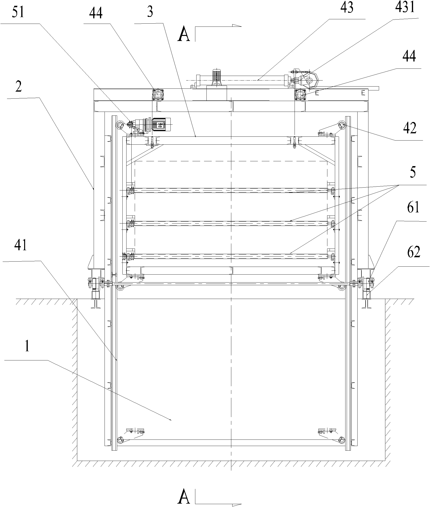
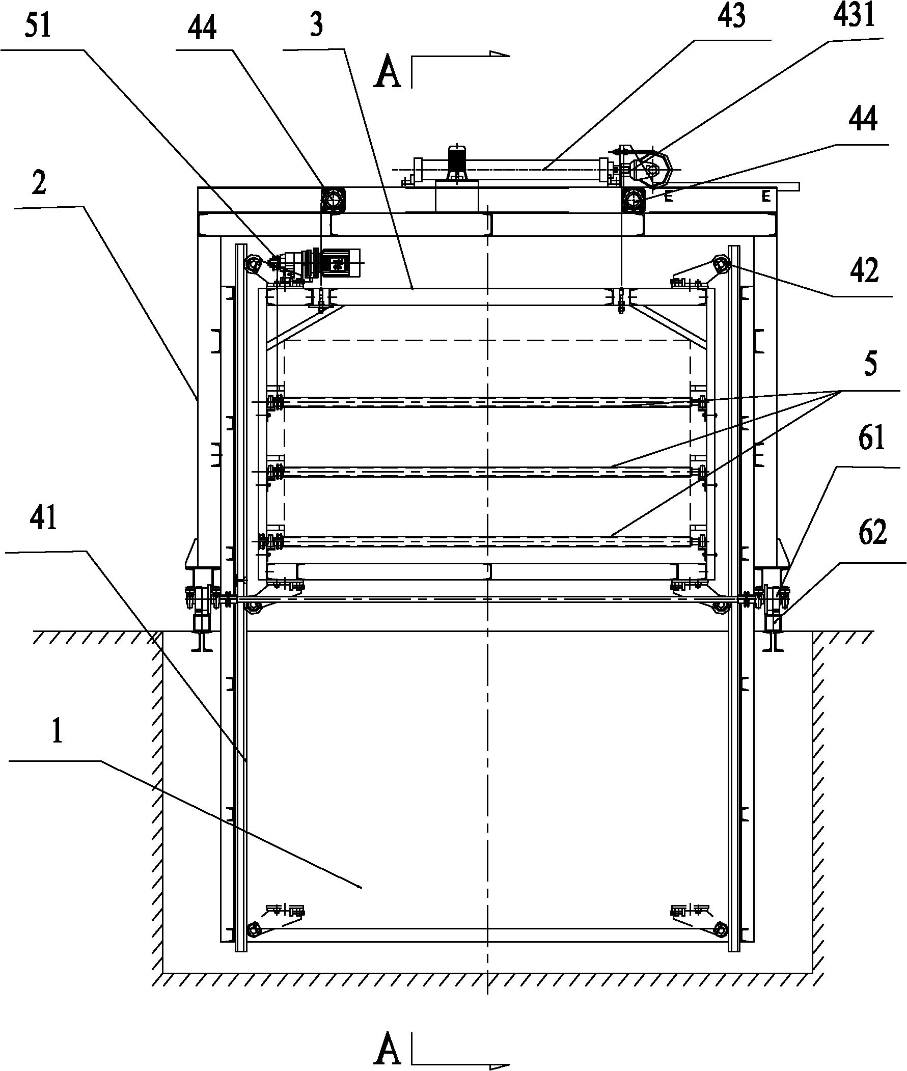
[0012] Such as Figure 1-2 The shown automatic quenching device includes a quenching tank 1, a support frame 2, a quenching frame 3, a lifting mechanism, a transmission roller 5 and a traveling mechanism, and the traveling mechanism is composed of a traveling wheel 61, a traveling guide rail 62 and a traveling driving cylinder 63. The support frame 2 is installed above the quenching tank 1, and the bottom corners are equipped with traveling wheels 61 in parallel, and the upper side of the quenching tank 1 is provided with a walking guide rail 62 corresponding to the traveling wheels 61; The cylinder piston 631 is connected with the bottom of the support frame 2 . The quenching frame 3 is located inside the supporting frame 2, and a lifting mechanism is provided between the quenching frame 3 and the supporting frame 2 to move the quenching frame 3 up and down. There are 2 pieces of 41, which are installed in parallel on the inner side of the support frame 2 and extend into the...

Embodiment 2

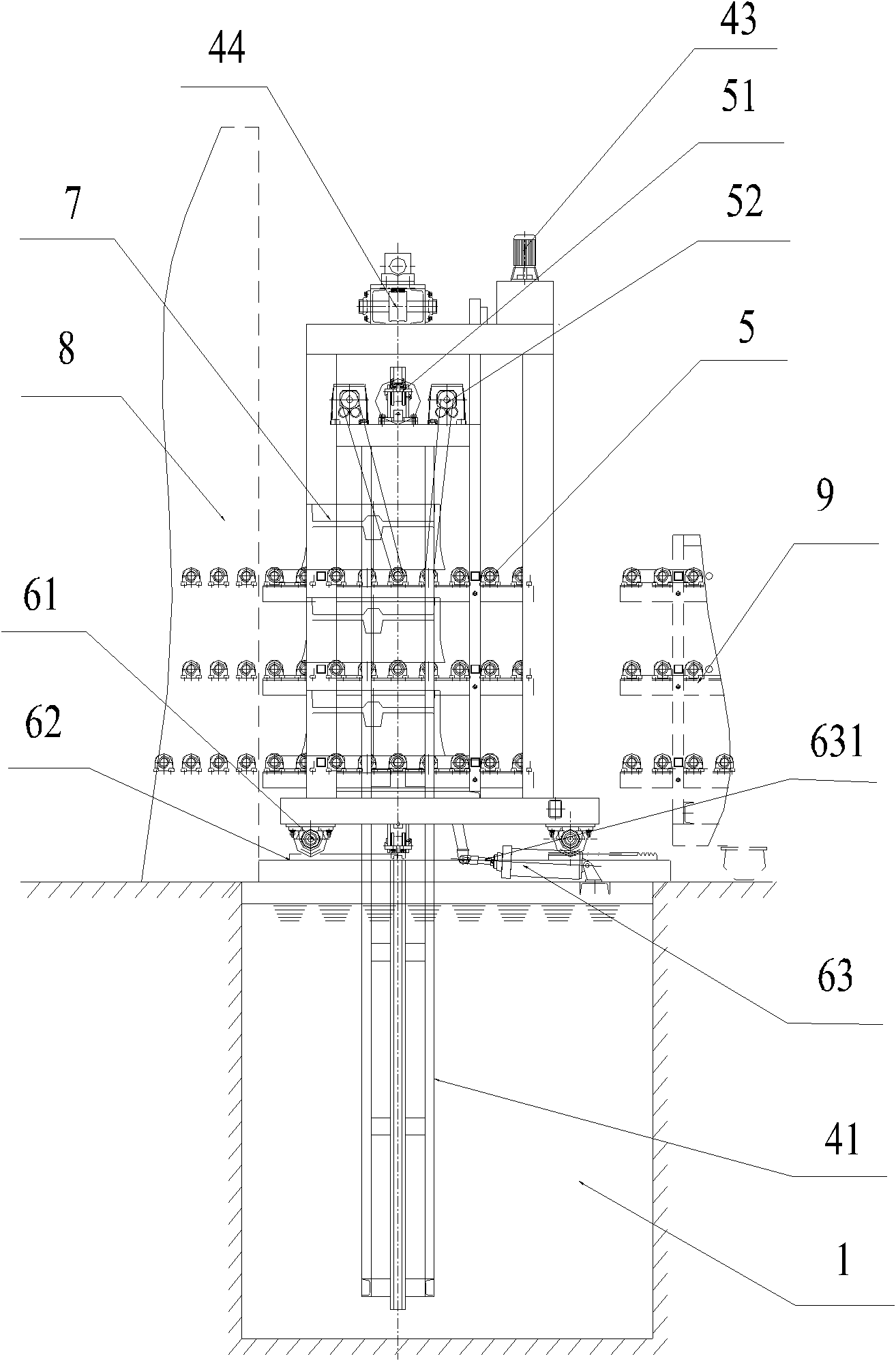
[0015] The difference from Embodiment 1 is that no walking mechanism is included, and the support frame 2 is installed above the quenching tank 1 . This device is close to the transmission frame 8 of the discharge port of the furnace body, and the hub 7 is directly transferred to the transfer roller 5, and the transfer roller 5 transfers the hub 7 to the quenching position. After the quenching time is over, the lifting mechanism will lift the quenching frame 3 above the liquid level of the quenching tank 1, and the transfer roller 5 will transfer the wheel hub 7 to the aging furnace drive frame 9 for the next process operation.


PUM


Abstract

The invention relates to an automatic quenching device, which comprises a quenching tank, a supporting frame, a quenching frame, a lifting mechanism, and a carrying roller, wherein the supporting frame is arranged above the quenching tank; the quenching frame is positioned inside the supporting frame; the lifting mechanism for making the quenching frame move up and down is arranged between the quenching frame and the supporting frame; and the carrying roller is horizontally arranged inside the quenching frame. The carrying roller is connected to a wheel hub which is quickly carried to a quenching position, and the lifting mechanism lowers the quenching frame to a position below the liquid level of the quenching tank. The automatic quenching device can quickly carry the wheel hub to the quenching position, can control the best quenching moment, and has high wheel hub quenching quality; besides, the automatic quenching device adopts the carrying roller to transfer the wheel hub and avoids local long-time high-temperature operation of a delivery mechanism, so the component damage is small and the later maintenance cost is low.

Description

technical field [0001] The invention relates to an automatic quenching device, in particular to an automatic quenching device for a hub. Background technique [0002] At present, the larger wheel hub manufacturing enterprises in China generally adopt the push-pull quenching process. After the push rod pushes the hub from the discharge port to the quenching position above the quenching tank, the hub descends and immerses in the quenching liquid for quenching. Because the speed of transferring the hub by the push rod quenching mechanism is relatively slow, the optimal quenching time of the hub is delayed, which not only wastes energy, but also affects the quality of hub quenching. At the same time, because the push rod quenching mechanism slowly pushes the wheel hub to the quenching position above the quenching water tank, the push rod operates at high temperature for a long time, the push-pull head is easily deformed and damaged, and needs to be replaced frequently, which inc...

Claims


Application Information

Patent Timeline
IPC IPC(8): C21D9/34C21D1/63
Inventor 张延波
Owner NANJING CHANGJIANG IND FURNACE TECH GRP CO LTD
Why Eureka
Try Eureka