Movable type hydraulic trash-cleaning machine

A cleaning machine and mobile technology, which is applied in the field of cleaning machines, can solve the problem of large differences in mechanical properties such as diameter, rigidity, toughness and curvature radius, complex structure of underwater cleaning mechanism, loose oil pipes, and insufficient tension. First-class problems, to achieve the effects of saving production costs, safe use, and stable operation

Inactive Publication Date: 2011-01-05
江苏佳佩环保机械设备有限公司
View PDF0 Cites 9 Cited by
  • Summary
  • Abstract
  • Description
  • Claims
  • Application Information

AI Technical Summary

Problems solved by technology

During this process, the oil supply and return pipelines of the hydraulic system and the rake bucket go down and up at the same time. This structure can simplify the underwater actuator and reduce the moving parts in contact with the sewage. Therefore, it is required that the oil supply and return pipelines and the wire rope lifting device must be synchronized. Due to the large difference in mechanical properties such as the diameter, rigidity, toughness, and radius of curvature of the oil pipe and the steel wire rope, the slack and tension of the oil pipe during the downward and ascent of the rake bucket vary, and even the oil pipe ...

Method used


Image

  • Movable type hydraulic trash-cleaning machine
  • Movable type hydraulic trash-cleaning machine
  • Movable type hydraulic trash-cleaning machine

Examples


Embodiment Construction

[0018] The present invention will be further described below in conjunction with accompanying drawings and embodiments.

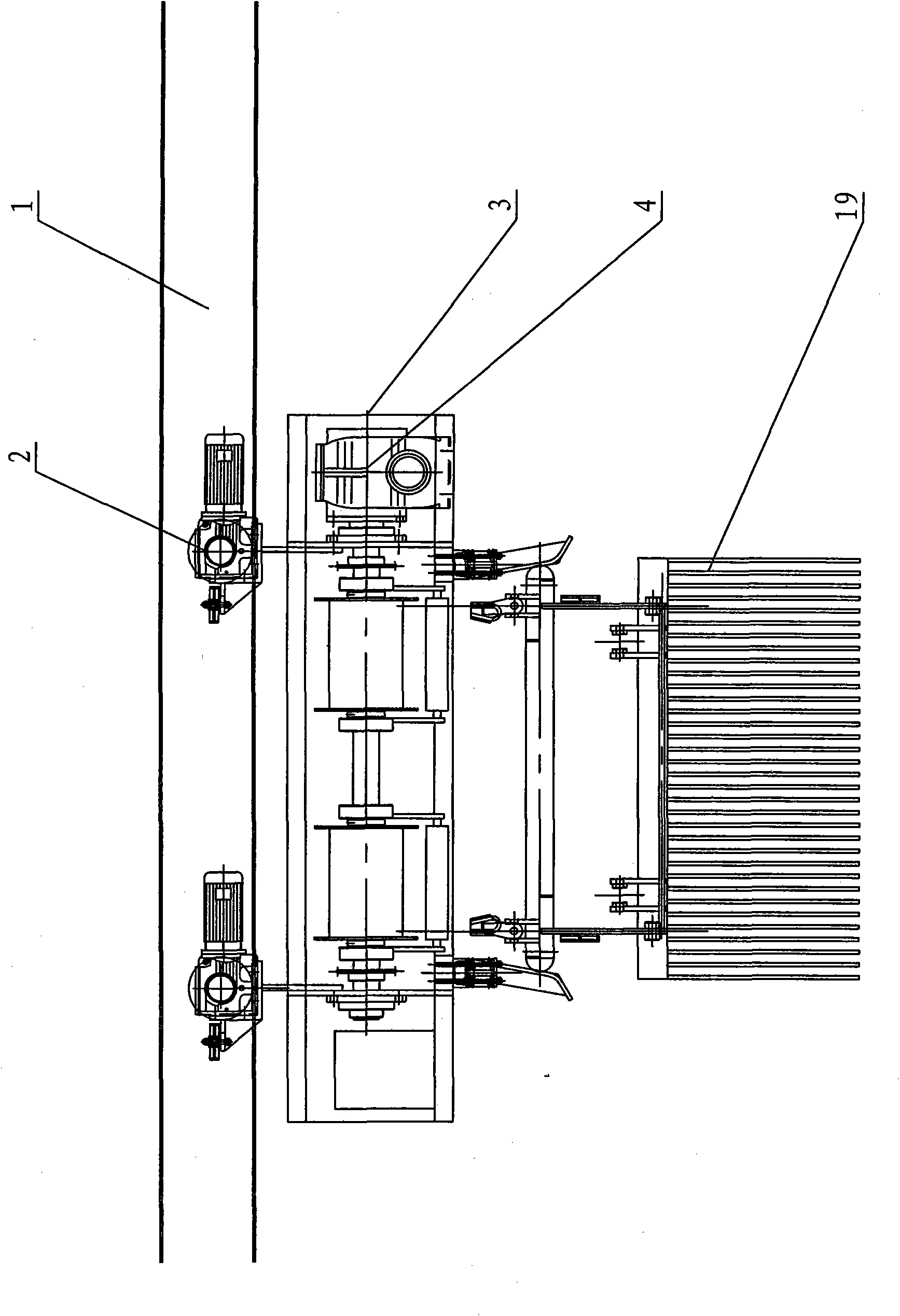
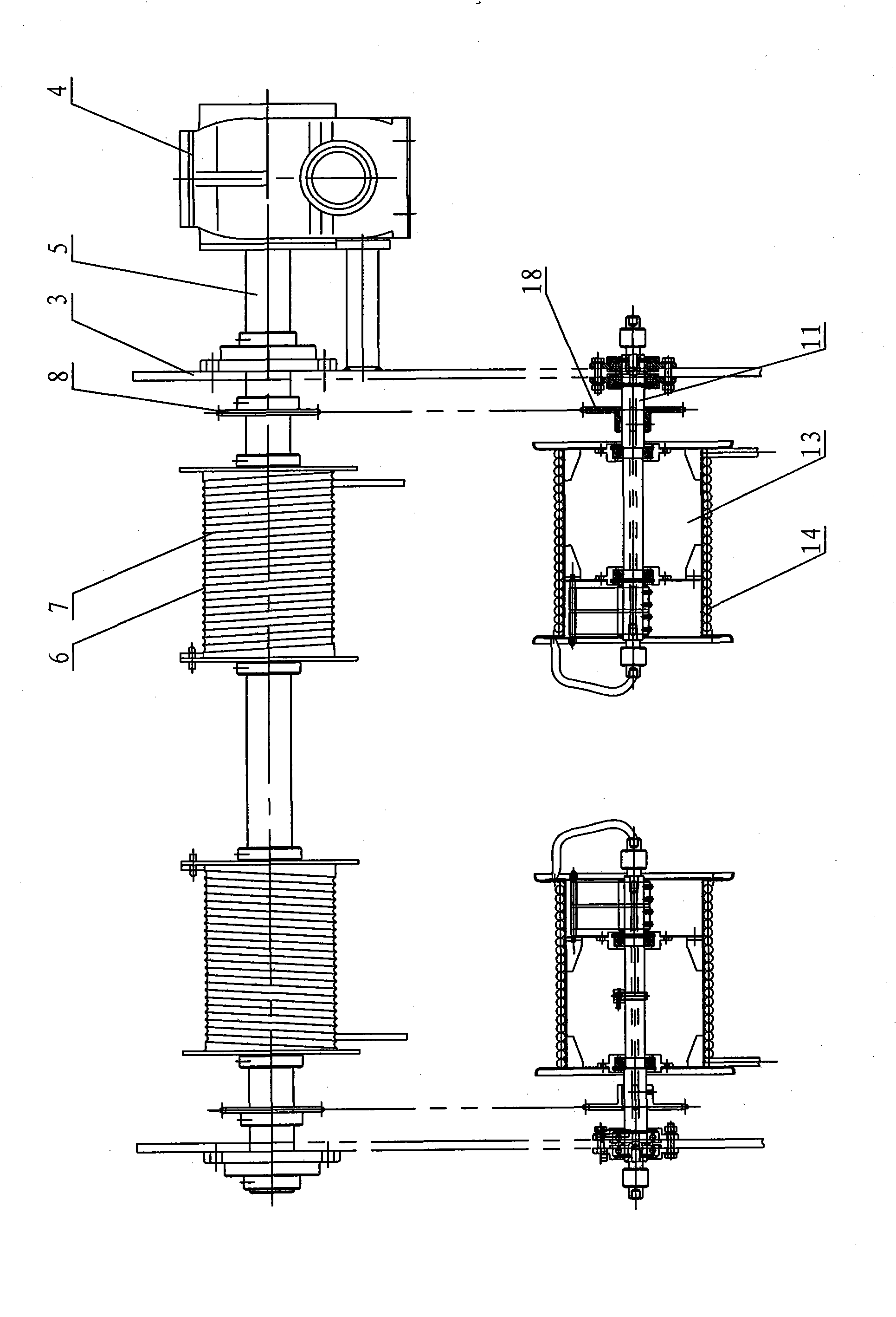
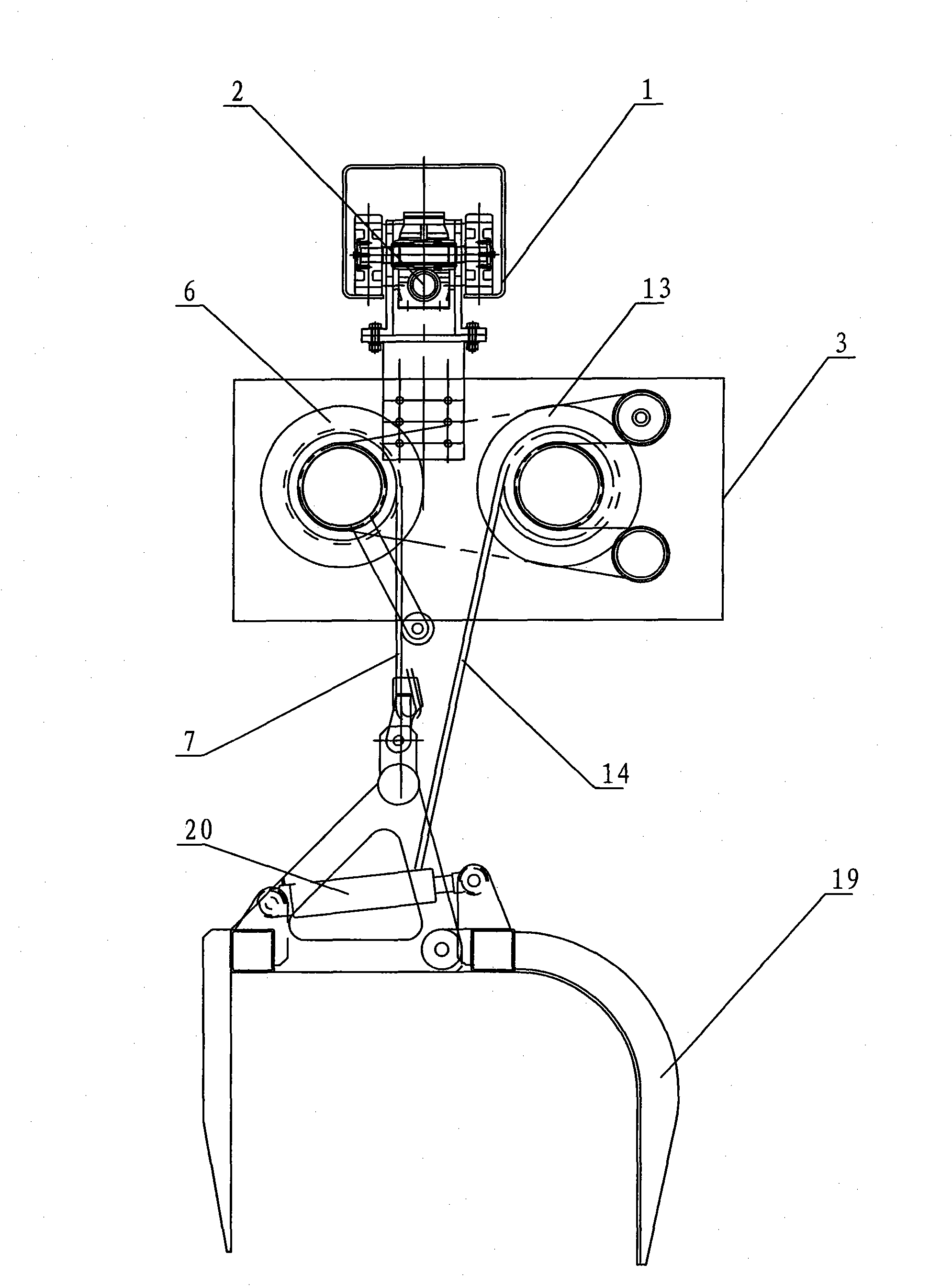
[0019] Figure 1-4 The mobile hydraulic cleaning machine shown mainly includes track 1, two travel motors 2, frame 3, drive motor 4, drive shaft 5, two wire rope reels 6, wire rope 7, two drive sprockets 8, Onboard hydraulic pump station 9, oil inlet rotary joint 10, driven shaft 11, two oil pipe reels 13, oil pipe 14, spring seat 15, mainspring spring 16, compensation rotary joint 17, two driven sprockets 18, Slag removal rake bucket 19, hydraulic oil cylinder 20, pin shaft 21. Two walking motors 2 are installed in the track 1 and walk in the track 1. The lower end of the walking motor 2 is connected to the frame 3; Two drive sprockets 8 and two wire rope drums 6 are symmetrically installed on the drive shaft 5 inside, and the wire rope 7 is wound on the wire rope drum 6; Two driven sprockets 18 and two oil pipe reels 13 are symmetrically installed on t...


PUM


Abstract

The invention relates to a movable type hydraulic trash-cleaning machine. The machine mainly comprises a travelling mechanism, a winding mechanism and a scraper bucket mechanism, wherein a travelling motor of the travelling mechanism runs in a track to drive the winding mechanism and the scraper bucket mechanism to move and work; a driving motor of the winding mechanism drives a wire rope reel to rotate and reel and release a wire rope through a driving shaft to realize the lifting of a deslagging scraper bucket; a driving chain wheel on the driving shaft of the winding mechanism drives a driven chain wheel through a chain to drive an oil tube winding drum to rotate and reel and release an oil tube, so that oil is supplied to a hydraulic oil cylinder to enable the deslagging scraper bucket to open and close; a clockwork spring is arranged on a driven shaft in the oil tube winding drum of the winding mechanism, when a trash-cleaning scraper bucket descends, the pre-tensioning force of the clockwork spring in the oil tube winding drum is released gradually, and when the trash-cleaning scraper bucket ascends, the clockwork spring of the oil tube winding drum is tightened gradually, so that the oil tube and the wire rope always descend and ascend synchronously and are consistent in tensioning and the phenomenon that the oil tube breaks away from the oil tube winding drum or is snapped is avoided; and therefore, the movable type hydraulic trash-cleaning machine has the advantages of safe and reliable running and long service life.

Description

technical field [0001] The invention relates to a sewage cleaning machine, in particular to a mobile hydraulic sewage cleaning machine, which is a mobile hydraulic sewage cleaning machine, which is used for cleaning dirt in multiple water inlet channels such as urban water supply, drainage, and water intake pumping stations, or on the grid surface of wide channels. Background technique [0002] The basic composition of the mobile hydraulic cleaning machine in the prior art is made up of traveling mechanism, slag removal rake bucket, lifting mechanism, hydraulic system and electric control system. The main working method is: the traveling mechanism moves to the upper part of the trash rack, the lifting mechanism puts down the slag removal rake bucket, and under the action of gravity, the slag removal rake bucket slides along the grid surface of the channel to the bottom of the channel, and the dirt intercepted by the grid surface is discharged from the top to the bottom of the...

Claims


Application Information

Patent Timeline
IPC IPC(8): E02B15/10
CPCY02A20/204
Inventor 刘圣武程中
Owner 江苏佳佩环保机械设备有限公司
Why Eureka
Try Eureka